This article will cover the creation of the plane’s animation, camera, and HUD. It answers one particularly tricky question: how can we make HUD elements line up correctly with a given angle?
Github at part-2
Animation
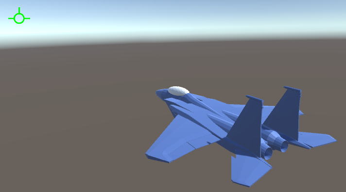
The animations for the control surfaces are pretty simple. Since the aerodynamic forces working on the plane are all faked, the position of the graphical elements don’t matter. We can simply move them in a way that looks good, without worrying about physics.
The animation code is then very simple. We simply take the player’s input on each axis and multiply that by a constant to get the rotation for each control surface.
rightAileron.localRotation = CalculatePose(rightAileron, Quaternion.Euler(deflection.z * maxAileronDeflection, 0, 0));
leftAileron.localRotation = CalculatePose(leftAileron, Quaternion.Euler(-deflection.z * maxAileronDeflection, 0, 0));
This calls the CalculatePose function, which is quite simple.
Quaternion CalculatePose(Transform transform, Quaternion offset) {
    return neutralPoses[transform] * offset;
}
neutralPoses is a dictionary that stores the original rotation of each control surface. That rotation is combined with the offset rotation to produce the final rotation.
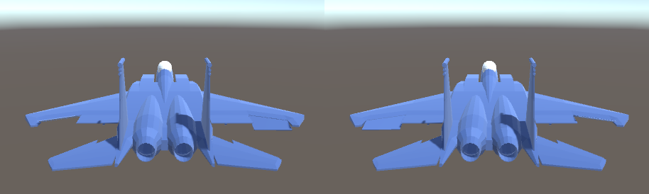
The afterburners are animated by scaling them. Under 75% throttle, the afterburner graphics are disabled. From 75% to 100% throttle, the afterburner graphics are scaled from .25 to 1.
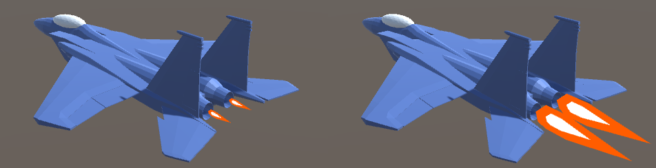
I also used a neat trick for the afterburner graphics. I placed two meshes one inside the other. Then I inverted the normals so that the inner mesh draws on top of the outer mesh. That gives a transparency-like effect without actually using transparency.
Camera
Being able to turn the camera is crucial during dogfights. The enemy plane will not always be directly in front of the player. The player should have some way to turn the camera and follow the enemy as both are moving and turning.
I chose to use an Ace Combat style camera. The player can look around using the right stick. Moving the stick all the way to one side will turn the camera in that direction. Holding the stick in any position will hold the camera in a certain rotation. When the player releases the stick, the stick returns to the center position and the camera returns to the forward facing rotation.
That is to say, while an FPS game lets the player control camera rotation speed, this game will allow the player to directly control camera rotation with the right stick.
var currentLookAngle = Vector2.Scale(lookInput, lookAngle);

var rotation = Quaternion.Euler(-currentLookAngle.y, currentLookAngle.x, 0);
var offset = rotation * cameraOffset;

cameraTransform.localPosition = offset;
cameraTransform.localRotation = rotation;
lookInput is the player’s input on the right stick. lookAngle is a pair of angles that define the limit of rotation on the X and Y axis separately. For example, a value of (170, 90) means the player can look up to 170 degrees to the left or right, and up to 90 degrees up or down. The player’s input is used to create rotation.
cameraOffset is the position of the camera when the stick is in the center. For example, a value of <0, 6, -20> defines the camera to be 6 meters above the plane and 20 meters behind.
The cameraOffset is rotated by rotation to find the position offset. The camera’s rotation is then set to rotation. This makes the camera spin around and always keep the plane in the bottom center of the screen.
However, I don’t use the player’s camera input directly to rotate the camera. Instead I use an exponential moving average (EMA) to smooth the input. Without the EMA, a player could release the stick and the camera would snap back to the center position in a single frame, which is jarring and disorienting. With an EMA, the camera will smoothly ease back into the center position. This smoothing will handle any large and fast camera movement.
An EMA is implemented like this:
average = (average * (1 - alpha)) + (target * alpha);
average is the result of the EMA. This value is stored between frames. target is the value we are trying to reach. alpha is a value that controls how strong the EMA smoothing is. One side of the sum is multiplied by (1 - alpha) and the other is multiplied by alpha. If alpha is chosen to be 0.5, then the new value will have 50% influence from the previous value and 50% influence from the target value. In other words, it will move 50% closer to the target each frame. If alpha is 1, then the previous value has 0% influence and the target value has 100%. This will cause the average to snap to exactly the target value each frame.
So an alpha value of 1 is equivalent to no smoothing, and any value less than 1 will apply stronger smoothing that takes longer to reach the target value.
Here is how an EMA is added to the camera code:
var targetLookAngle = Vector2.Scale(lookInput, lookAngle);
lookAverage = (lookAverage * (1 - lookAlpha)) + (targetLookAngle * lookAlpha);

var rotation = Quaternion.Euler(-lookAverage.y, lookAverage.x, 0);
We use lookAverage instead of lookInput to construct the camera rotation.
Finally, there’s one more thing that moves the camera. When the plane turns, the camera should also turn by a small amount. If the player rolls right, the camera should roll left slightly, to make the turning motion more obvious. This is accomplished by taking the plane’s current angular velocity and constructing another rotation. The angular velocity is smoothed with another EMA and then multiplied by a constant.
The final camera code looks like this:
var rotation = Quaternion.Euler(-lookAverage.y, lookAverage.x, 0);  //get rotation from camera input
var turningRotation = Quaternion.Euler(new Vector3(-avAverage.x, -avAverage.y, avAverage.z) * movementScale);   //get rotation from plane's AV

cameraTransform.localPosition = rotation * turningRotation * cameraOffset;  //calculate camera offset position;
cameraTransform.localRotation = rotation * turningRotation;                 //calculate camera rotation
HUD
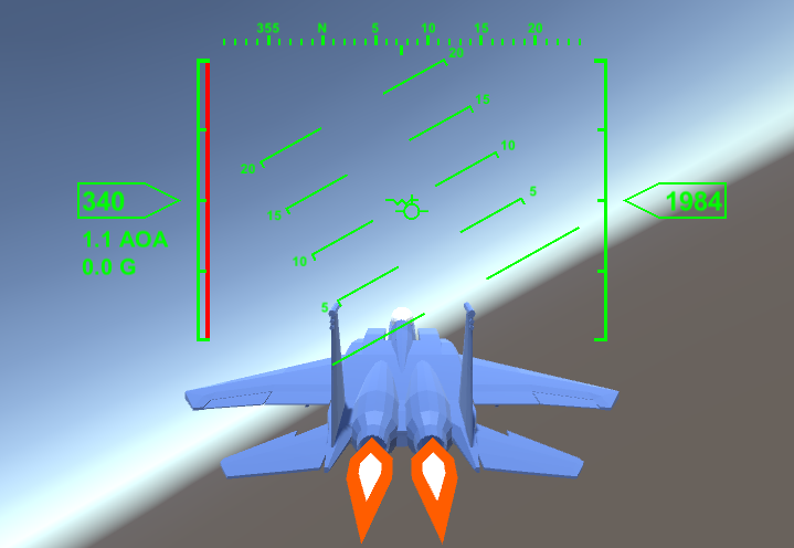
The first issue is to decide what information to show to the player. A player in a dogfight might pull all kinds of chaotic maneuvers, turning in every direction as they chase the enemy. All of that turning can disorient the player. So the HUD for the plane should at the very least contain information about the plane’s orientation relative to the world. The player should be able to understand this information at a glance.
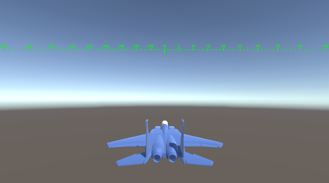
A lot of video games have a compass that tell the player which direction they’re facing. But that only covers one axis of possible rotation (yaw). A plane needs to tell the pilot about roll and pitch as well. Real world fighter jets use a pitch ladder for this purpose. A pitch ladder is essentially a compass that is oriented vertically instead of horizontally. The pitch ladder is rotated to match the world’s vertical axis, so if the pilot rolls 30 degrees to the left, the pitch ladder rolls 30 degrees to the right. This will tell them how far up or down their nose is pointing, as well as how much they are rolled to the side.
There needs to be an indicator that tells the player where exactly on the pitch ladder their nose is pointing. This indicator is called the boresight. The boresight will stay fixed in the center of HUD while the pitch ladder moves around it.
Another indicator needs to show what direction the plane is moving. Recall from Part 1 that a plane does not always fly exactly in the direction it is facing. If it has a positive AOA, then the nose is pointing slightly above the direction of travel. This is shown by the velocity vector indicator.
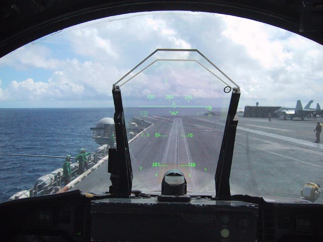
Consider the above picture of a real F/A-18’s HUD. At the horizon, where the water and sky meet, is a long green line. The circle on the horizon line is the velocity vector. Since the plane is stationary, the vector just points forward. The W shaped symbol below is the boresight indicator. Below that are the markers showing -5 degrees and -10 degrees pitch. Above the horizon is the compass.
We can tell from the HUD that the nose is pointing slightly below the horizon and that the plane is facing compass heading ~260 degrees. Since the markers on the pitch ladder are level, we know that the plane has 0 roll.
In order to make the HUD more intuitive to read, we need to ensure that markers on the pitch ladder are placed sensibly. The horizon line should always be shown on the horizon, even when the plane changes pitch. The -5 degrees marker should cover any object that is 5 degrees below the horizon from the pilot’s point of view.
If the pilot is flying and points the nose 10 degrees downwards, the boresight stays in the center of the HUD. The pitch ladder moves upwards until the horizon line is over the real horizon and the -10 degree marker lines up with the boresight.
Aside from the pitch ladder and compass, there need to be a few other indicators. The HUD needs to show speed and altitude. It should also show other information like AOA and current G Forces.
HUD Implementation
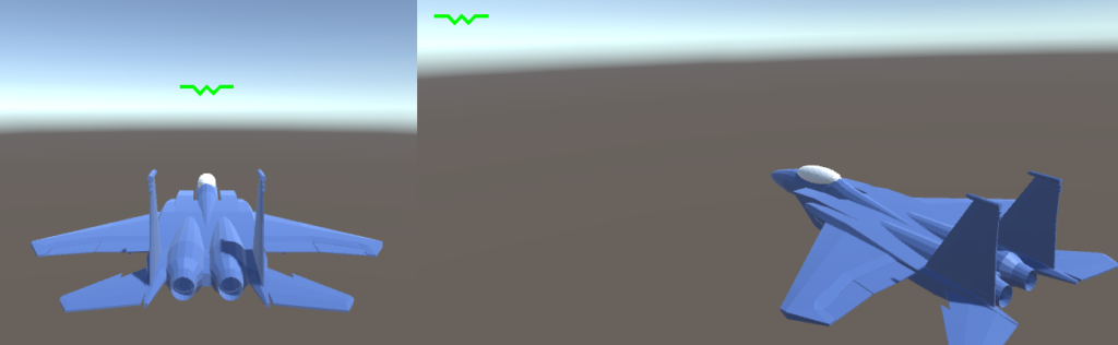
Since the player can move the camera around, we have to account for that while drawing the HUD. The boresight is supposed to show the direction the plane is facing, so if the player rotates the camera to the side, the boresight should move in the opposite direction.
Luckily, Unity3D provides an API to handle this for us. We can use the method Camera.WorldToScreenPoint to position the boresight. We choose a position some distance in front of the plane (in world space) and call WorldToScreenPoint to find where the position is on the HUD (in screen space).
We find the screen space position like this:
Vector3 TransformToHUDSpace(Vector3 worldSpace) {
    var screenSpace = camera.WorldToScreenPoint(worldSpace);
    return screenSpace - new Vector3(camera.pixelWidth / 2, camera.pixelHeight / 2);
}
This calculates the screen space position for the HUD element by calling the WorldToScreenPoint function and then shifting it by half of the screen’s size. This shifts the origin of screen space so that (0,0) is at the center of the screen.
Then the world space position is calculated like this:
var hudPos = TransformToHUDSpace(cameraTransform.position + planeTransform.forward);
Boresight and Velocity
The world space position is constructed from the plane’s forward vector added to the camera’s position.
If we constructed the world space position using the plane’s position instead of the camera, then the boresight would appear to be a finite distance in front of the plane.
This causes a parallax effect. You can lessen the effect by placing the indicator further along the plane’s forward direction, but using the camera’s position avoids it entirely.
We calculate the velocity indicator using the same function.
var hudPos = TransformToHUDSpace(cameraTransform.position + velocity);
Compass and Pitch Ladder
The compass and pitch ladder are more complicated to implement. As mentioned above, the markings on them should match with the actual angle they represent. The horizon line should always be shown on the horizon. The 5 degree line should appear 5 degrees above the horizon and so on.
Choosing where to place markers is not straightforward. Consider this situation: the camera has a horizontal field of view (FOV) of 90 degrees. Then the compass could cover the range -45 degrees to 45 degrees. However, the marks on the compass will not be spaced equally far from each other. The camera will cause distortion towards the edge of the screen.
As you can see, the markers at the center of screen are close together and the markers at the edge are far apart. This is due to the nature of the projection matrices used by Unity3D and other game engines. You can imagine the pixels on the screen as being rays cast from the camera into the game world. If each ray is rotated 1 degree from it’s neighbor, it will create a perspective effect. However, the screen is a flat plane in front of the camera, not a circle. So rays further from the center of the camera will be increasingly far from their neighbors.
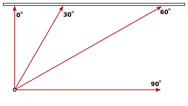
In this image, the rectangle at the top is the screen and the dot at the bottom is the camera. The ray marked 0 degrees is the center of the camera’s field of view. The 30 degree ray is a small distance from the 0 ray. The 60 degree ray is much further from 30, than 30 is from 0. The 90 degree ray never intersects the screen.
The distortion of the screen follows the curve of tangent(x). There is 0 distortion at 0 degrees. As the angle approaches 90 degrees, the distortion approaches infinity. This is of course mirrored when the angle is negative.
Here is the code to place markers following this distortion:
public static float TransformAngle(float angle, float fov, float pixelHeight) {
    return (Mathf.Tan(angle) / Mathf.Tan(fov / 2)) * pixelHeight / 2;
}
We calculate the distortion at our desired angle with Mathf.Tan(angle). We divide that by the maximum possible distortion at the edge of the screen Mathf.Tan(fov / 2). This is then multiplied by the size of the screen. We divide the FOV and the screen size by 2 since 0 degrees is in the center of the screen. So a 90 degree FOV really spans from -45 to 45 degrees.
We use the vertical FOV and vertical screen size, even when calculating horizontal distortion. The horizontal and vertical distortion are always equal.
Using this function, we can then place the markers on the compass and pitch ladder.
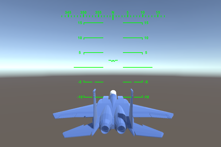
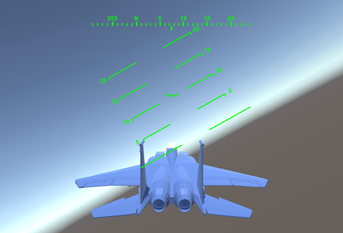
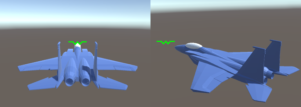
As you can see the pitch ladder rolls in the opposite direction of the plane. That keeps the horizon line level with the real horizon. The pitch ladder tells the player their roll and pitch and makes it easier to orient themselves during a chaotic dogfight.
The values used to select a position on the compass or pitch ladder are easy to find. Unity3D automatically provides pitch, roll, and yaw values using Transform.eulerAngles.
//from Compass.cs
//yaw == rotation around y axis
float yaw = planeTransform.eulerAngles.y;

//from PitchLadder.cs
//pitch == rotation around x axis
//roll == rotation around z axis
float pitch = -planeTransform.eulerAngles.x;
float roll = planeTransform.eulerAngles.z;
The yaw and pitch values are used to select which compass or pitch ladder markers are displayed. The roll value just rotates the pitch ladder.
The rest of the HUD elements are trivial. Altitude is the plane’s height, transform.position.y. Speed is the plane’s forward speed, plane.LocalVelocity.z. The AOA and G meters read from plane.AngleOfAttack and plane.LocalGForce.y. The throttle bar just shows the current throttle setting, plane.Throttle.
Conclusion
Now that we have a HUD, the player can know all of the data needed to fly their plane. The airspeed, altitude, and pitch ladder are particularly important for managing energy. The player can use the AOA indicator or velocity vector indicator to know their AOA, which tells them how much induced drag they’re facing at the moment.
The progress up to here is covered by the tag part-2 in the Github repo.
The next part will cover weapons and AI.
1 thought on “Creating a Flight Simulator in Unity3D Part 2: HUD”
Comments are closed.