This post will cover the use of PID controllers in video games.
If you’ve ever used your car’s cruise control, flown a quadrocopter, or piloted a rocket, then there’s a good chance that you’ve used a PID controller. A PID controller is a type of control loop that’s used for automation.
PID controllers are flexible since they can handle changing target values and changing external conditions. The PID can be configured by it’s designer to respond to changes in different ways. For example, one system might respond with fast, snappy movements, while another uses slow and gentle movements. Both can be achieved just by reconfiguring the PID controller.

Intro
PID stands for proportional, integral, derivative. These are the three terms used to calculate the controller’s output.
PID controllers have countless applications. In abstract, they can be used to drive any system with variable input. A sensor on the PID controller reads the current state of the system, and uses that to calculate the next input for the system.
A car’s cruise control uses a PID to maintain a desired speed in changing road conditions. The sensor is the speedometer and the output is the throttle position. For a drone, the sensor is an altimeter and the output is the motor power. For a rocket, the sensor is a gyroscope and the output is the position of the control surfaces.
In games, PIDs can be used for a simulation of any of the real world purposes. It can also be used to give a human-like feel to an AI. For example, it can be used to control the aim of an AI character in an FPS, to avoid an “aimbot” feel.
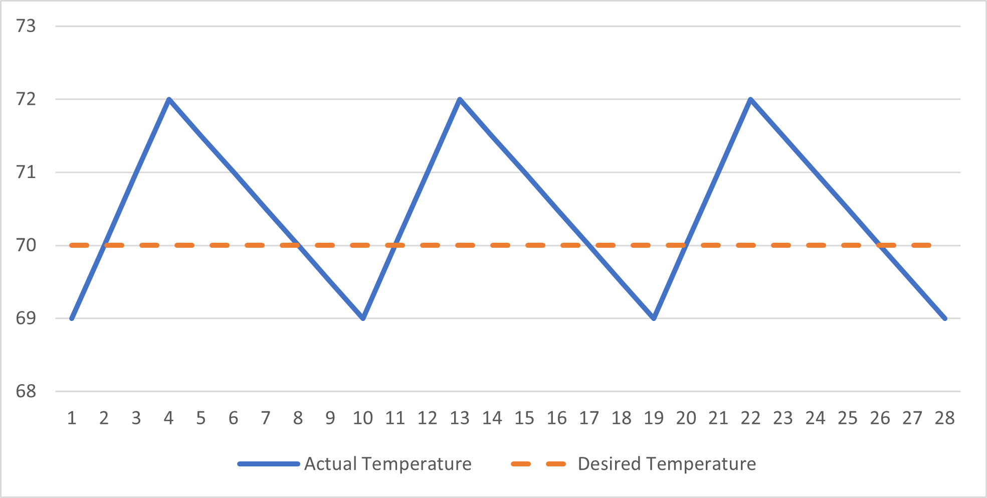
But let’s start by examining something a little simpler. A thermostat in a regular house is an example of a simple “on-off” controller. The user sets a desired temperature. The thermostat (the controller) measures the current temperature. If the temperature is too low, it activates the heater (the system) until the desired temperature is reached. The heater can only be on, 100% power, or off, 0% power.
In pseudocode, the logic would look like this:
while (true) {
    temp = getTemp();

    if (temp < desiredTemp) {
        heaterOn();
    }

    if (temp > desiredTemp + 2) {
        heaterOff();
    }
}
On-off controllers aren’t very precise, but they don’t need to be. The thermostat might aim for a temperature that is within 1 or 2 degrees of the desired temperature. When it shuts off the heater, it will take some time before the room temperature falls below the desired temperature.
An on-off controller is acceptable for a thermostat, since the user probably won’t mind small temperature variations. But it isn’t precise enough to use for a car’s cruise control. Imagine if your cruise control only used 0% or 100% throttle. This would create a jerky, uncomfortable, and unsafe experience.
A PID controller is used when you need more precision than just on or off. The basic idea is to calculate a more precise value to control the system. An on-off controller has exactly two states: on and off, or 0 and 1. A PID controller can produce states in a range such as [0, 1].
For a thermostat that allows more precision than just on and off, the logic for a PID controller could look like this:
while (true)
    temp = getTemp();

    P = calculateP(temp) * proportionalGain;
    I = calculateI(temp) * integralGain;
    D = calculateD(temp) * derivativeGain;

    setHeaterPower(P + I + D);
}
Just like an on-off controller, a PID controller uses feedback from the system to calculate the next input. The three terms are the proportional, integral, and derivative terms, shortened to P, I, and D. These terms are calculated using different methods to handle different conditions. Then, they’re summed up to produce the input which is passed to the heater.
The proportionalGain, integralGain, and derivativeGain are constants chosen by the designer of the PID controller to fine tune the behavior. The constants must be tuned for a specific system to get good behavior from the PID controller.
If a gain constant is set to 0, then that term becomes 0 and has no effect on the final result. Such a controller is referred to by omitting the terms that are disabled. For example, if derivativeGain is 0, then it’s called a PI controller.
I’ve implemented all of the concepts into this example project on Github. It’s written in C# for Unity3D. The demo is also playable in browser at this page on itch.io. While PID controllers are mainly used in industrial automation, they have plenty of uses in games.
Implementation
PID controllers are incredibly simple to implement. Here, we’ll build a PID controller in C#.
class PIDController {
    public float proportionalGain;
    public float integralGain;
    public float derivativeGain;

    float Update(float dt, float currentValue, float targetValue) {
        //TODO: implement this
    }
}
The interface is quite simple. dt is the timestep of the simulation. At 60 FPS, this is 1/60th of a second. currentValue is the measurement of the system’s current state. This is the feedback part of the controller. targetValue is the target value.
First, we calculate the error which is the difference between the target value and the current value. This is the basis for all of the computed terms.
float error = targetValue - currentValue;
Proportional
Then we compute the P term. This is the main term and the simplest. The error is simply multiplied by the gain.
float P = proportionalGain * error;
This means the P term will be proportionally as large as the error. If the error doubles, the P term doubles. The P term is almost always enabled and should be the first term to tune if tuning the PID manually.
This can cause a problem if the PID is driving a system that has momentum. A heater that produces no heat when the input is zero has no momentum. But a drone that uses propellers to accelerate upwards will have upwards momentum even when the input is zero and the propellers stop spinning.
This means the P term can cause some systems to overshoot, since they will have momentum when the error reaches zero. In fact, if the P term can apply positive and negative forces and the system has no friction (or other way to lose energy), then the P term will act like an ideal spring and will oscillate forever around the target value.
Oscillation is one of the main problems you can face when using a PID controller. Luckily, most systems have some kind of friction, and in a video game you can control the friction force directly. However, the derivative term will give you more explicit control over the oscillation.
Another issue to watch out for is saturation. The system likely has a limit for how large of an input it can accept. For example, a motor may only allow input in the range [-1, 1] which is from full reverse to full forward speed. If the P term (or any term) is larger than the allowed range then the input is saturated.
This means changes in the P term may be ignored. For example, if the P term is 100 when the max input is 1, then the input is clamped to 1. When the P term falls to 50, the input is still clamped to 1, so the system does not change behavior.
Saturation is unavoidable and normal when dealing with large error values. It just means that one term can dominate the others if the conditions are right. For example, if the P term is 100 and the other terms are -10, the sum is 80, so the input is still saturated at 1. Small changes in the other terms are ignored since the P term is so large.
Derivative
I’m going to cover the derivative term next, since it’s important for handling oscillation. If the P term acts as a spring, the D term acts as a dampener. The D term calculates the rate of change (derivative) of the error value and applies a damping force. To do this, we store errorLast, which is the error value from the last update.
float errorRateOfChange = (error - errorLast) / dt;
errorLast = error;

float D = derivativeGain * errorRateOfChange;
Consider a system where the current value is 0 m, the target value 100 m, and the current velocity of the system is 0 m/s. With a large error of 100 m, the P term will be applying a strong force towards the target value. As explained above, the P term will accelerate the system until the error is 0, then it will overshoot and begin oscillating.
The D term applies a force away from the target value, based on how fast the error is changing. The rate of change of the error is simply the opposite of the system’s velocity. When the system isn’t moving the error does not change. When the system is moving at +5 m/s, the error is changing by -5 m/s.
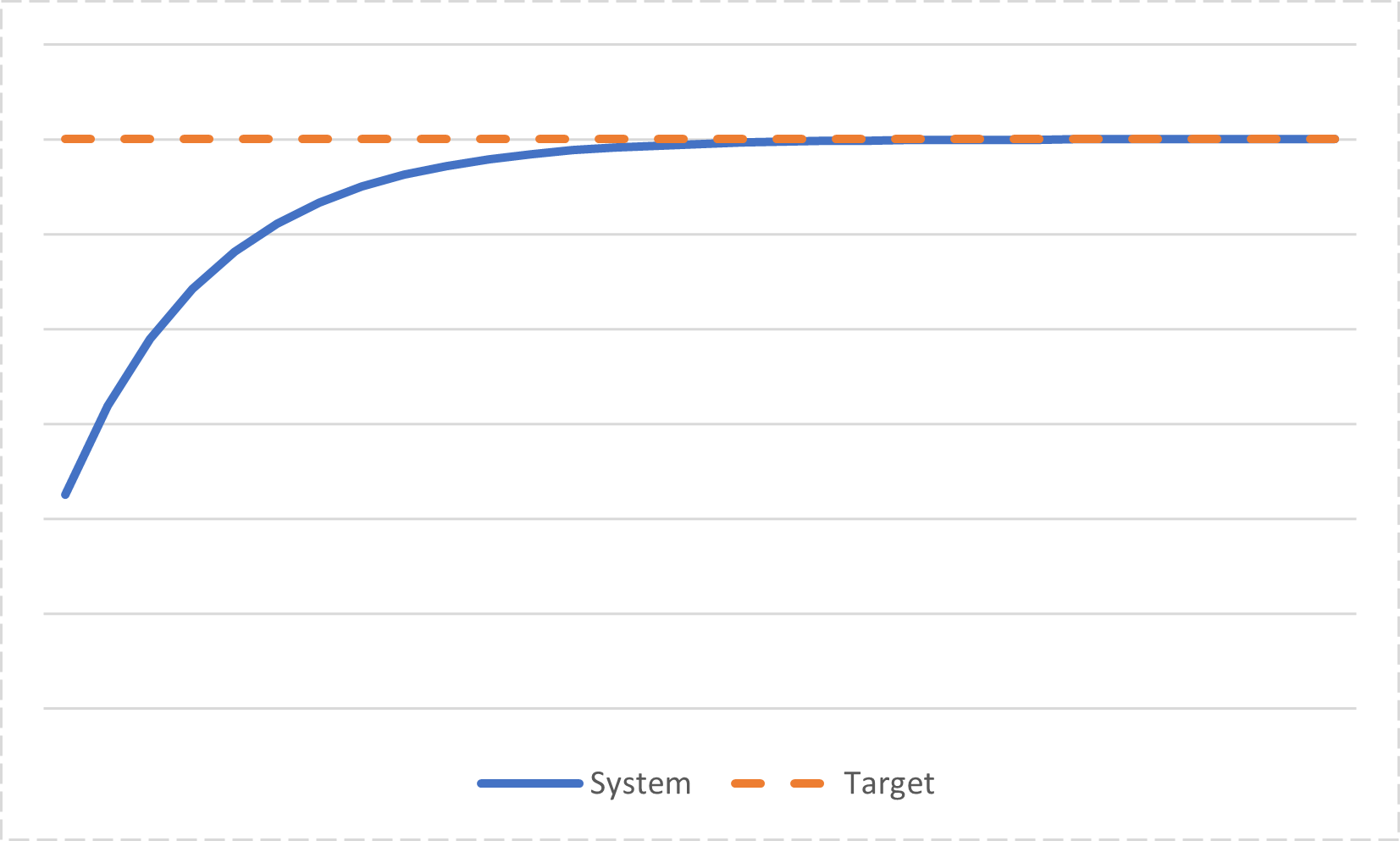
This means the D term provides a braking force that gets stronger the faster the system is moving. Compare it to the P term, which is stronger the further the system is from the target. A controller that uses both P and D terms will find a balance point where the P and D terms are equally strong (in opposite directions), so the system moves at a steady speed. Then as the system approaches the target, the P term gets weaker, meaning it will slow down. Slowing down means the D term also becomes weaker, restoring the balance between the forces.
In other words, the D term smoothly slows down the system as it approaches the target, limiting overshoot.
Using larger values for derivativeGain will cause the system to ease into the target value over a longer period. If the target value is moving, the D term will cause the system to lag a little behind the target.
Note that there can still be overshoot if the D term is weak. The D term will prevent the system from oscillating forever, but limited oscillation is still possible. It will just get smaller and smaller each time. The system will eventually converge.
There are some limitations with the above code. Imagine the system still has a target of 100 m. When the system reaches the 75 m mark, the target value is then changed to 200 m. This causes the error to suddenly jump from 25 m to 125 m. While the error was steadily decreasing earlier, for this frame alone, the error spikes to a large value, then continues decreasing in future frames.
This is called a derivative kick and it can cause some instability and other unwanted behavior. While the D term normally applies a force opposite to the P term, a derivative kick can briefly apply a force in the same direction as the P term.
Remember earlier when I said the rate of change of the error is the opposite of the system velocity? This is true except when the target value changes. If the target value changes, the velocity remains steady, but the error rate of change experiences the derivative kick.
So you can remove the derivative kick by using the velocity to calculate the D term, instead of the error. Just store valueLast instead of errorLast. (Remember, currentValue is passed as an argument to Update())
float valueRateOfChange = (currentValue - valueLast) / dt;
valueLast = currentValue;

float D = derivativeGain * -valueRateOfChange; //note the negative sign here
Note the negative sign there.
Most PID controllers will probably want to remove the derivative kick, but in some niche cases, it may be desirable. So we can add a switch to let the user change the behavior of the D term, depending on their needs.
//calculate both D terms
float errorRateOfChange = (error - errorLast) / dt;
errorLast = error;

float valueRateOfChange = (currentValue - valueLast) / dt;
valueLast = currentValue;

//choose D term to use
float deriveMeasure = 0;
if (derivativeMeasurement == DerivativeMeasurement.Velocity) {
    deriveMeasure = -valueRateOfChange;
} else if (derivativeMeasurement == DerivativeMeasurement.ErrorRateOfChange) {
    deriveMeasure = errorRateOfChange;
}

float D = derivativeGain * deriveMeasure;
There’s one final problem with the D term. This term depends on the error or value from the previous iteration. What happens on the first iteration, when there is no previous data? Well, C# initializes member variables to 0, so errorLast and valueLast will both be zero. So the error rate of change effectively becomes this:
(error - 0) / dt
And likewise with the value rate of change. For both values, the initial iteration can cause a large D term for a single frame, much like a derivative kick.
The solution is to skip calculating the D term on the first iteration. This can be done by adding a new member.
public bool derivativeInitialized;
Then this variable is checked before calculating the D term
float deriveMeasure = 0;
if (derivativeInitialized) {
    if (derivativeMeasurement == DerivativeMeasurement.Velocity) {
        deriveMeasure = -valueRateOfChange;
    } else if (derivativeMeasurement == DerivativeMeasurement.ErrorRateOfChange) {
        deriveMeasure = errorRateOfChange;
    }
} else {
    derivativeInitialized = true;
}

float D = derivativeGain * deriveMeasure;
Finally, a method is added to reset this variable.
public void Reset() {
    derivativeInitialized = false;
}
Reset() would be called if the system is moved by external means (such as being teleported) or if the PID controller has been turned off for a long period of time.
Integral
Finally we compute the I term. This is called the integral term because it integrates (sums) the error over time. The longer an error exists, the stronger the I term gets.
We add a new member, integrationStored, to the class definition. Then we add the current error value multiplied by the timestep on each update.
integrationStored = integrationStored + (error * dt);
float I = integralGain * integrationStored;
integrationStored can be positive or negative. If error is 0, then integrationStored doesn’t change. Maintaining an error in one direction will eventually lead to a large value in integrationStored. Crossing the target value will start decreasing the value stored.
The I term is important for eliminating steady state error. Steady state error can occur when there is a constant external force acting on the system, such as gravity, or when the target value is constantly moving.
Consider the above system with a PD controller (no I term yet). Gravity applies a constant force of 9.81 newtons downwards. The rocket propelled box can apply a force of up to 15 newtons upwards (but not downwards). The target altitude is by target 3, but the box does not reach this.
If the box reached the target value, the P term would fall to zero and the box would begin falling. The D term cannot hold it at the target, since a velocity of 0 means the D term is zero. Instead, the box settles at an error of ~0.65 meters below target 3. This is where the P term balances with the force of gravity. At an error of 0.65, the P term produces a throttle input of 0.65. This produces a thrust of ~0.65 * 15N = ~9.81N, enough to counter gravity.
The box will settle at 0.65 even if it starts above or below the target value. This is the steady state error.
The way to eliminate this is by using the I term. The I term has a “memory” of the past error states. If the error value is large, the P term will immediately respond to it, while the integral term will slowly ramp up.
Now with the I term enabled, the integrator eventually stores a value of 0.65, while the error falls to 0. So the P term is reduced to 0, while the I term is large enough to counter gravity.
Using an I term introduces additional problems though. When the error is reduced to 0, the P term will also be 0, but the I term can still be large. This can cause even worse overshoot than the P term, a condition called integral windup. Not only can the momentum carry the system past the target value, but the integration will be “wound up” by storing a large value. It will take time to “unwind” this integration, which can carry the system even further past the target value.
One solution is to have a limit for how large the integrationStored can be, positive or negative.
integrationStored = Mathf.Clamp(integrationStored + (error * dt), -integralSaturation, integralSaturation);
This clamps the value to the range defined by integralSaturation. This is another value that must be chosen by the designer of the PID controller. A good starting point for this value is to set it equal to the saturation of the system. If the system only accepts inputs in the range [-1, 1], then the integralSaturation should be set to 1.
This is why the Int. Saturation field is set to 1 in the above video.
This solution still allows for windup, but it’s so small that it’s quickly corrected. This is probably good enough for most uses. There are other more advanced anti windup measures, but I won’t be covering them here.
The value of integralSaturation has to be large enough to eliminate the steady state error. If we set it to 0.5, for example, it wouldn’t be strong enough to counter gravity by itself. The box would settle at an altitude below the target, though it would be closer than if the I term were disabled.
Homework question: If the integrationGain were set to 2, what value would the integralSaturation need to settle at? This will be on the exam.
Output
Finally, the three terms are summed together and clamped to the range [outputMin, outputMax].
float result = P + I + D;

return Mathf.Clamp(result, outputMin, outputMax);
outputMin and outputMax should be set to the limits of input for the system. For the box used in the horizontal demo, the limits are [-1, 1]. The vertical demo is limited to [0, 1].
Rotating Systems
PID controllers can be used to control a rotating system, such as a turret. The problem is, in a rotating system, 355 degrees and 5 degrees are only 10 degrees apart, but a naive PID controller would see these values as being 350 degrees apart. This would cause major problems for the PID controller when the current value or target value crosses the 0 value.
The solution is to calculate the difference between the angles, accounting for the point where 360 degrees wraps around to 0 degrees. We also need the output to have the range [-180, 180] for the PID logic to work correctly.
We add a new function, AngleDifference:
float AngleDifference(float a, float b) {
    return (a - b + 540) % 360 - 180;   //calculate modular difference, and remap to [-180, 180]
}
The formula for angular difference is (a - b + 360) % 360. This finds the difference between the angles and adds 360, to make sure the result is always positive. This would return values in the range [0, 360], so we need to remap by adding 180 to the term in the parenthesis, and subtracting 180 after the modulus. This is (a - b + 360 + 180) % 360 - 180, which is simplified to the above code. Now, the output range is [-180, 180].
We add a new function, UpdateAngle to the PID class for handling rotating systems. The error, errorRateOfChange, and valueRateOfChange are calculated using the new AngleDifference function. All other PID logic remains the same.
public float UpdateAngle(float dt, float currentAngle, float targetAngle) {
    float error = AngleDifference(targetAngle, currentAngle);

    ...

    //calculate both D terms
    float errorDelta = AngleDifference(error, errorLast);
    float errorRateOfChange = errorDelta / dt;
    errorLast = error;

    float valueDelta = AngleDifference(currentAngle, valueLast);
    float valueRateOfChange = valueDelta / dt;
    valueLast = currentAngle;
}
Our PID controller can now correctly handle rotating systems.
// from Horizontal.cs
float input = controller.Update(Time.fixedDeltaTime, rigidbody.position.x, targetPosition.x);

// from Turret.cs
float input = controller.UpdateAngle(Time.fixedDeltaTime, currentAngle, targetAngle);
Tuning Demo
Using the turret, we can walkthrough the process of tuning a PID controller by hand.
The system starts with all gain constants set to 0, so the turret doesn’t move.
We set the P-gain to 1, so the turret starts tracking the box.
This causes some subtle oscillation, so we set the D-gain to 1.
This fixes the oscillation, but now the turret is lagging significantly behind the box. We can reduce the D-gain to 0.1 to reduce how much it lags.
Finally, we can set the integral saturation and I-gain to both to 1, this will reduce the small amount of steady state remaining.
Conclusion
PID controllers are a simple but powerful method of automatically controlling a system. It can’t be used to solve every problem, but it works well for any physically based system.
The itch.io demo allows you to tune the PID gains in real time. You can use this to test how different values affect the behavior of the system.
There are plenty of more advanced uses of PID controllers that I didn’t cover here. Some ideas that you might want to research on your own are: automatic PID tuning, dynamic PID tuning, nested PID controllers, and other controller types from the field of control theory.
There are also more limitations that I didn’t cover. For example, a real world PID controller may have to deal with noise on the sensor, but this demo in Unity3D doesn’t. A real system may have a slow response to changing input, but this demo has instant response. These problems can be handled (or deliberately added) without changing the core logic of how the PID controller operates.
2 thoughts on “PID Controllers in Unity3D”
Comments are closed.