In this post, I will describe a shader for Unity3D that recreates the look of a reflex sight. A reflex sight projects the image of it’s crosshair to some distance in front of the viewer. Red dot sights holographic sights are both types of reflex sights, they only differ in the crosshair used for aiming.
The distance of the crosshair may be finite, such as 100 meters, or it may be infinite. When you move your head side to side, the crosshair will appear to be in the distance. It does not look like a red dot painted on the glass. This video is an example of the effect in real life.
There are multiple ways to achieve this effect. One method is to use a separate object for the crosshair and use stencil masking so that it only draws it behind the lens. However I don’t like the idea of using two objects or using the stencil buffer for a minor effect.
My solution was to use a single object (the lens) and a shader effect to change the UVs of a crosshair texture. This is much simpler to implement. The resulting shader acts like a reflex sight focused to infinity.
The code is available at this Github repo.

The Effect
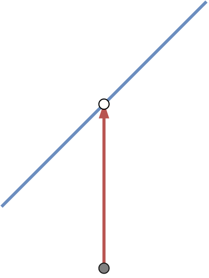
To understand how this works, consider the image below. The grey dot is the player’s camera. The white dot is the sample being rendered. The blue line is the lens. The red line is the line from camera to sample.
In the image below, a second red line is added past the lens. The green line is the opposite of the normal of the lens. Both of these lines are directions with a length of 1.
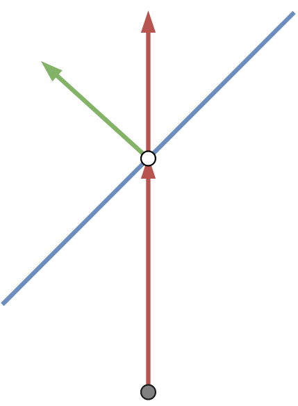
The difference between these lines is used to find an offset into the texture.
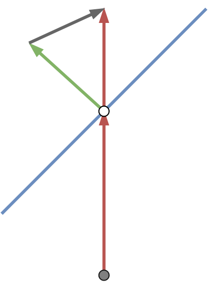
The offset’s Z component is discarded (Z is up in these images). This leaves a 2D vector that is used to sample from the texture.
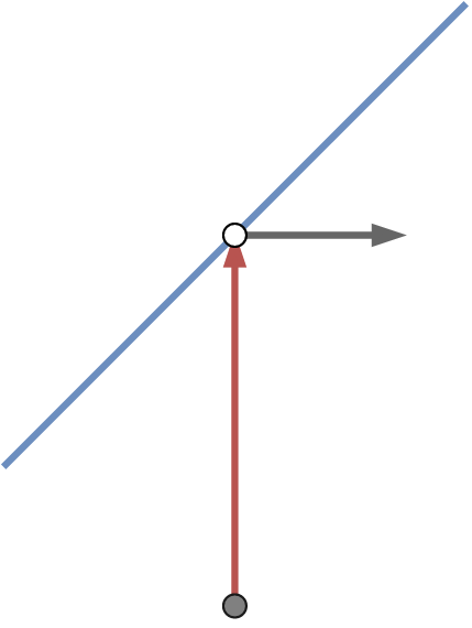
The slight difference in angle between two different samples will produce two slightly different sample locations. This is what allows the entire crosshair image to be shown on the lens. This process only approximates the offset needed. However when the camera is almost aligned with (the opposite of) the lens normal, the error isn’t noticeable.
If we stopped here, there would be one glaring error: The shader would not rotate the crosshair image. Notice how the crosshair is always aligned with the screen, not with the lens.
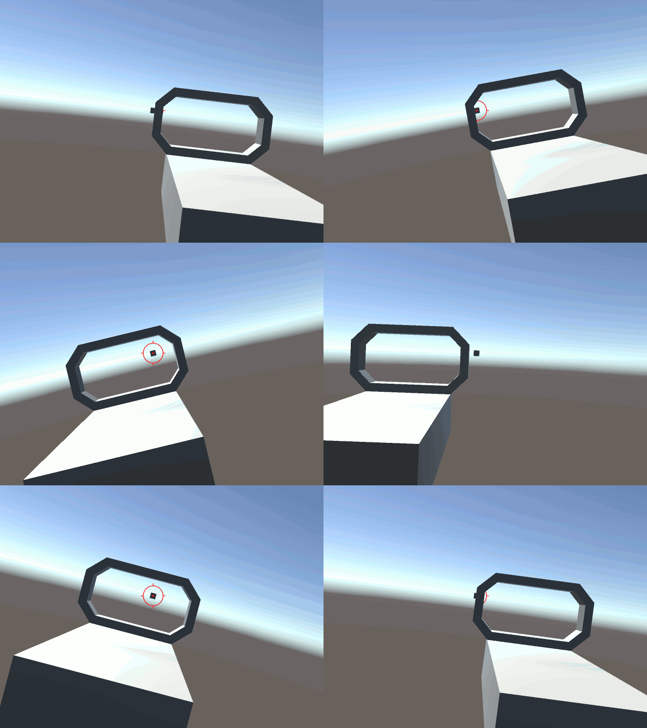
That happens because the above steps all calculate the texture offset in eye space. To fix this, we need to transform the offset into tangent space. The shader now correctly handles the case where the lens is rotated.
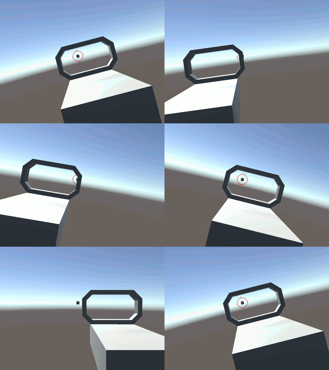
The Implementation
The code for this project can be found at this Github repo as a Unity3D project. You could easily implement this effect in other engines, as long as the shader has all of the required data. This effect is implemented in the file Reflex.shader.
This effect does not use the UVs of the lens. All you need for this shader is the position, normal, and tangent. o.vertex holds the position transformed into clip space. o.pos, o.normal, and o.tangent are all transformed into eye space. Then these values are passed to the fragment shader.
v2f vert (appdata v) {
    v2f o;
    o.vertex = UnityObjectToClipPos(v.vertex);
    o.pos = UnityObjectToViewPos(v.vertex);         //transform vertex into eye space
    o.normal = mul(UNITY_MATRIX_IT_MV, v.normal);   //transform normal into eye space
    o.tangent = mul(UNITY_MATRIX_IT_MV, v.tangent); //transform tangent into eye space
    return o;
}
The fragment shader extracts these values. normal is the opposite of the green vector in the images above. cameraDir is the red vector. Note that cameraDir is the direction from eye space origin to i.pos. The origin is left out of it’s calculation since it’s equal to (0, 0, 0).
offset is calculated from cameraDir - -(normal). This is simplified to use addition instead of subtracting a negation. offset is the grey vector in the above images.
float3 normal = normalize(i.normal);    //get normal of fragment
float3 tangent = normalize(i.tangent);  //get tangent
float3 cameraDir = normalize(i.pos);    //get direction from camera to fragment, normalize(i.pos - float3(0, 0, 0))

float3 offset = cameraDir + normal;     //normal is facing towards camera, cameraDir - -normal
The normal and tangent values are used to calculate a TBN matrix. This is used to transform offset into tangent space.
float3x3 mat = float3x3(
    tangent,
    cross(normal, tangent),
    normal
);

offset = mul(mat, offset);  //transform offset into tangent space
Then the UVs for the texture sample are calculated by dropping the Z component of offset. Texture Scale is a material property used to change the size of the crosshair image (called _TexScale below). The resulting UV would be (0, 0) if the camera and the lens normal were perfectly aligned. The UV is shifted by (0.5, 0.5) to place that sample at the center of the image.
float2 uv = offset.xy / _TexScale;      //sample and scale
return tex2D(_MainTex, uv + float2(0.5, 0.5));  //shift sample to center of texture
You will need to play with the Texture Scale property. A Texture Scale of 1 will project the image out to a size that fills about 60 degrees of the camera’s FOV. The crosshair effect will not scale as the camera moves away from the sight.
Alternate Effect
The above implementation projects the crosshair image to infinity. I also made an version that projects the image to a finite distance. This version is in the file Reflex2.shader.
This version uses the UVs of the mesh and adds another material property, Depth (called _Depth). This property controls the distance the image is projected to by changing the magnitude of offset.
The UVs of meshes are typically in the range of [0, 1] on both axes. The offset would be (0, 0) when the camera and lens are aligned. So the shader shifts the UVs by (-0.5, -0.5) before the texture scaling is applied. The UV is shifted back when sampling the texture.
float2 uv = (i.uv - float2(0.5, 0.5) + (offset.xy * _Depth)) / _TexScale;   //sample and scale
return tex2D(_MainTex, uv + float2(0.5, 0.5));                              //shift sample to center of texture
This is the alternate version of the shader. Notice how the crosshair seems to be at some distance between the sight and the target.
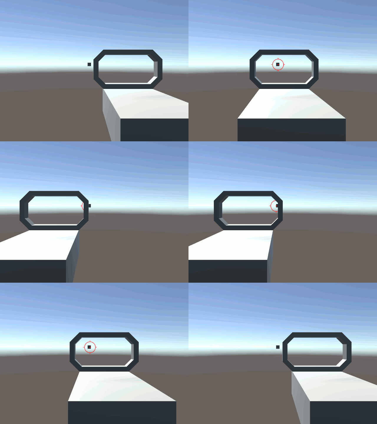
Depth does not correlate to meters. I have no idea what it correlates to. The apparent depth of the image also depends on the UVs of the mesh. If all of the UVs were squished into the same point at (0.5, 0.5) and Depth was equal to 1, this version will behave identically to the above version.
If Depth is equal to 0, then the image will appear to be painted on the lens, like a regular texture.
I don’t know what this version with finite depth could be used for, but I made it accidentally while developing the main version. Maybe someone else can find a use for it.
Conclusion
Vector spaces are hard. I should have paid more attention in my Linear Algebra classes.