I’ve been playing Ace Combat and Project Wingman recently. This inspired me to write my own flight simulator using Unity3D. I wanted to make a flight sim with more depth than the arcade flight sims, while still being accessible.
You can think of realism as a spectrum. On one end is Ace Combat and at the other is more serious sims like Digital Combat Simulator. While researching I found Tiny Combat by Why485. This game sits somewhere in the middle of the spectrum, which is basically exactly what I want. The game requires the player to understand concepts like energy management without needing several semesters worth of classes to get the plane off of the ground. It’s got a pretty slick art style too.
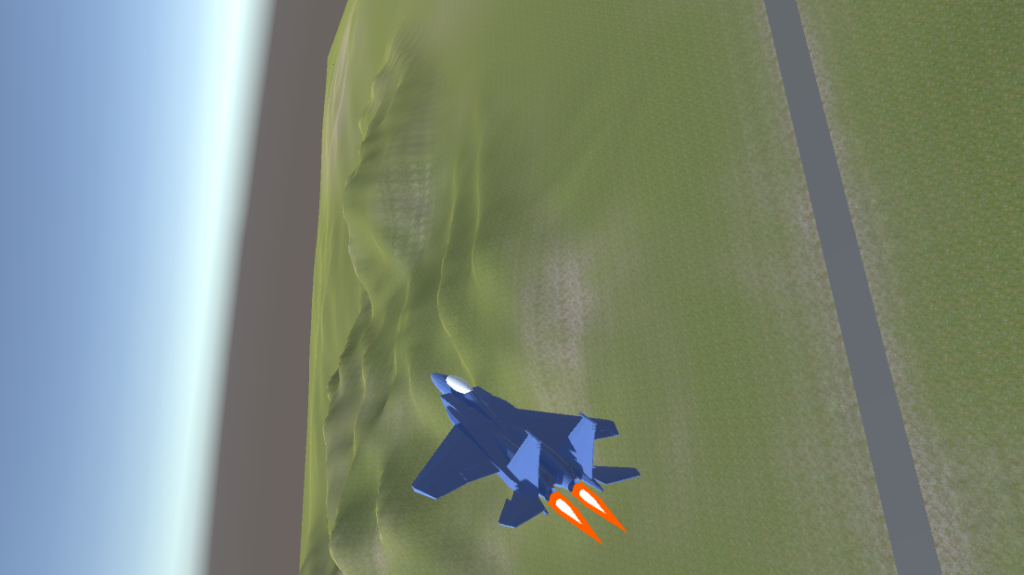
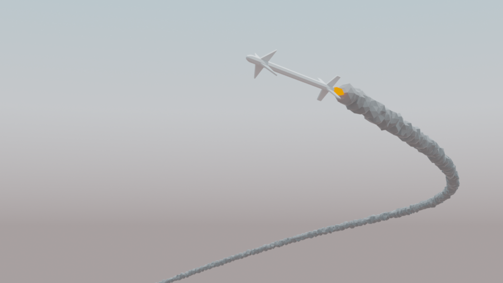
So I set out to make my own. Here’s a demo based on what this blog series will cover:
This post is also available in video form: https://www.youtube.com/watch?v=7vAHo2B1zLc
Here is the Github repo for this project, at tag part-1.
Note that the above video is not the same project as the content of this article or the itch.io game. The video includes a lot of assets that I don’t have license to redistribute. However the flight model is largely the same and the F-15 model is the same.
The Goal
The goal is to create a flight model that contains somewhat realistic forms of the following:
- Drag
- Lift
- Angle of Attack
- Induced Drag
- G-Force and G-Force limiter
- The “Corner Speed”
- Energy management
Additionally, I’d like to add a HUD, weapons, and a simple AI that’s capable of dogfighting the player while also respecting the above concepts. The AI should have all of the same capabilities and limitations as the player. These will be added in later parts.
There are some features that I don’t want to implement. I’m not going to simulate individual aerodynamic surfaces, add a complex damage model, or realistic weapon physics. Those are all deep rabbit holes in and of themselves. I’d like to focus on creating a basic plane for now.
The Physics of Flight
A plane maintains stable flight by balancing several forces. The plane can speed up or slow down, climb or descend, and turn by creating imbalances in these forces.
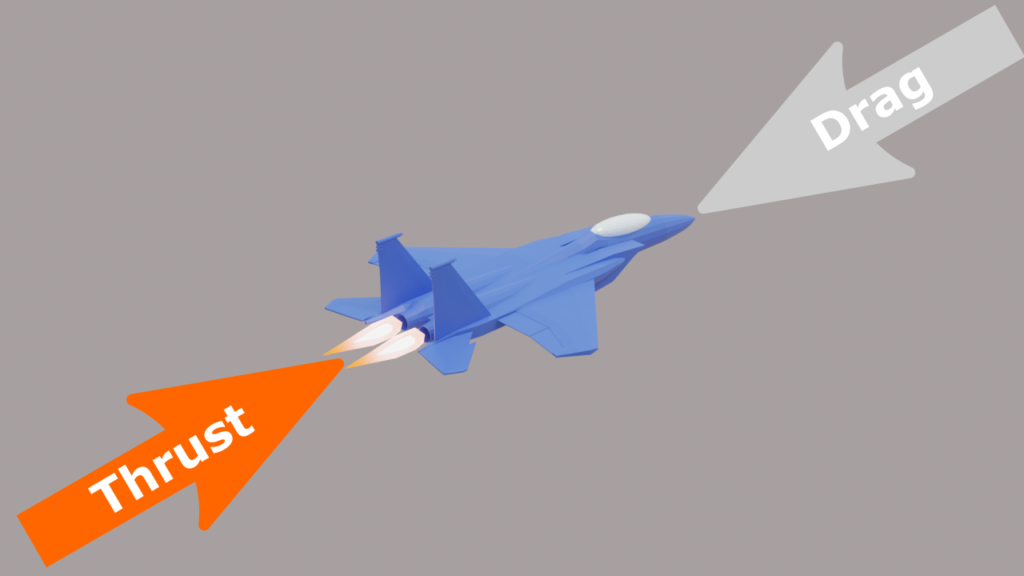
Thrust and Drag
Drag causes the plane to slow down. The engines provide thrust which causes the plane to speed up. When drag and thrust are equal, the plane flies at a constant speed. Drag increases quadratically with speed, so going twice as fast requires four times as much thrust.
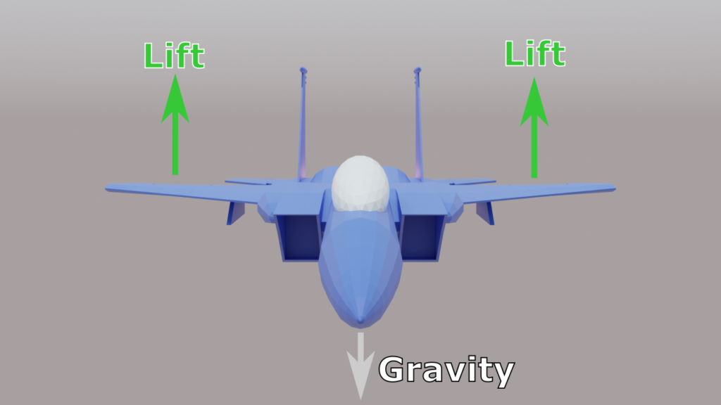
Lift
Gravity constantly pulls the plane downwards. Air flows over the wings and generates lift, which pulls the plane upwards. Lift depends on speed, so a higher speed generates more lift. When gravity and lift are equal, the plane flies at a constant altitude. If the plane’s speed is too low, then lift drops, gravity begins winning the fight, and the plane stalls. Additionally, the plane can deploy flaps, which create even more lift at the cost of increased drag. The increased drag limits the use of flaps to low speed.
Induced Drag
Whenever a surface produces lift, it also produces induced drag. The more lift, the more induced drag. Flying straight and level produces little induced drag and turning produces a lot. Induced drag causes the plane to lose speed, limiting how much the plane can turn before it loses too much speed and stalls.
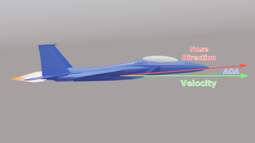
Angle of Attack
Lift also depends on Angle of Attack (AOA), which is the angle between the direction the plane’s velocity is pointing, and the direction the plane’s nose is pointing. An AOA of zero degrees produces zero lift. A larger AOA creates more lift, up to a point. If the AOA exceeds that point, for example at 15 degrees, then the lift drops and the plane stalls. A negative AOA produces negative lift, which pushes the plane downward.
In level flight, the nose will not point exactly horizontal. It will point a few degrees above that, creating a non zero AOA. The AOA required for level flight grows smaller as the plane’s speed increases.
Control Surfaces
The plane turns by creating an imbalance of lift. The imbalance is created by control surfaces. The plane has several control surfaces on the wings, the horizontal stabilizers, and the vertical stabilizers. The control surfaces alter the amount of lift generated by the part it’s attached to.
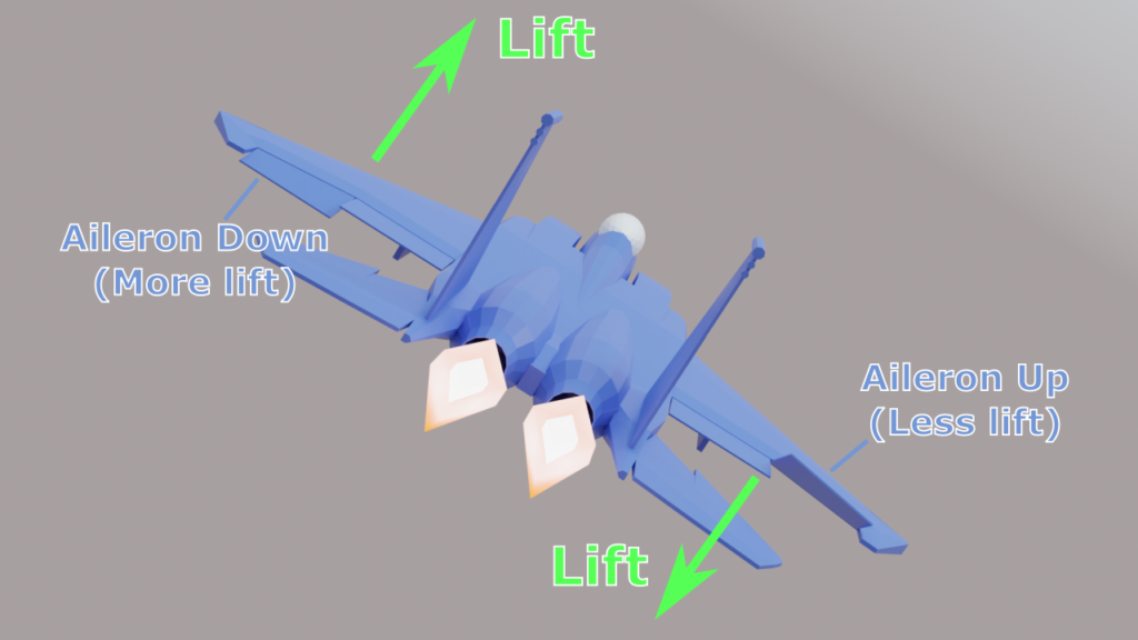
Ailerons are control surfaces on the wings. When the aileron moves down, the lift increases. When the aileron moves up, the lift decreases or even goes negative. So when one aileron goes up and the other goes down, the net effect is a torque that causes the plane to roll.
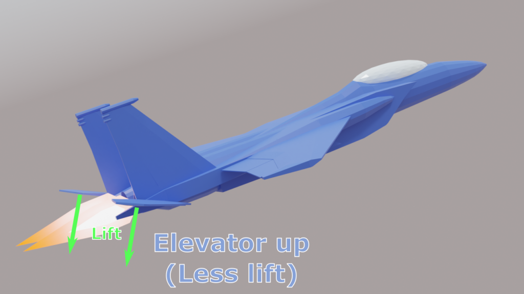
The horizontal stabilizers at the rear of the plane are essentially just mini wings. When flying normally, they produce some extra lift to fight against gravity. The control surfaces here are called elevators. When the elevators move, it changes the lift of the horizontal stabilizers. Since the stabilizers are at the rear of the plane, the lift force creates a torque that causes the plane to pitch it’s nose upwards or downwards.
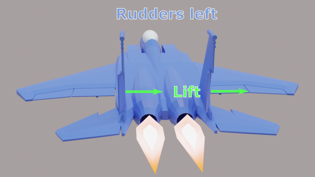
A vertical stabilizer is, again, another wing with a control surface called a rudder. However since it’s oriented vertically, the lift it produces does not fight gravity. Instead that lift only pulls the rear sideways and controls that plane’s yaw.
When all of the control surfaces are in their neutral positions, the plane is in steady flight. When some combination of control surfaces are moved into a deflected position, the plane turns. The strength of the turn depends on speed, just like the lift. At low speeds, the control surfaces are weaker. At higher speeds, the control surfaces are stronger.
G Forces and G Limiter
The plane is also limited by the squishy human piloting it. When the plane turns, it subjects the pilots to a G Force that pushes them into the seat, or lifts them up, or pushes them side to side. The G force created by a turn depends on how tight the turn is and the speed of the plane. So at low speed, a slight turn (in terms of degrees/second) will produce a slight G force. If you double the speed, the G force doubles, so even the same slight turn will produce significant G forces.
When flying straight and level, the pilot feels 1 G of force pulling them straight down, gravity. When pitching upwards, the pilot feels extra Gs pulling downwards. This is called positive G force. With enough positive G forces, a human heart can no longer pump blood upwards into the brain, causing the pilot to blackout. In real life, a fighter pilot with special training and equipment can sustain 8-10 G for a brief period.
Negative G force is even worse. Negative G forces occur when pitching downwards and pull the pilot upwards. Instead of blood being pulled away from the head, blood is instead forced into the head, causing a much more dangerous condition called redout. This is why planes turn by pitching up and rarely make strong pitching down maneuvers. As far as I can tell, the limit for humans seems to be about -4 G.
To avoid blackouts or worse injuries, planes have a G Limiter. This will automatically reduce the strength of the turn if the pilot gives a large input, since that would create a large G force. For example, the G limiter may limit the plane to making 8G turns, even if the plane is capable of 16G. So at higher speeds, the G limiter will be the main limit to how fast the plane can turn.
Corner Speed
The G limiter creates a corner speed, the optimum speed for turning. This is the slowest speed where the G limit can be reached. Below the corner speed, the turn rate is limited by the strength of the control surfaces. Above the corner speed, the turn rate is limited by the G limiter. Flying near the corner speed will give the plane the fastest possible turn.
Energy Management
All of these concepts combine to create a performance envelope for the plane. It must fly at some minimum speed to create enough lift to overcome gravity. The plane has a maximum speed determined by drag. The plane has a corner speed that the pilot wants to fly at, but turning will cause the speed to drop from induced drag.
This introduces the concept of energy. The plane has energy, which is the sum of kinetic energy from it’s current speed, and potential energy from it’s current altitude. You need energy to turn. You can build energy over time by flying in a straight line, increasing kinetic energy. You lose energy from drag, and induced drag. You can convert kinetic energy into potential energy by climbing upwards. This reduces speed and increases altitude. You can convert potential energy back into kinetic by diving. This increases speed and reduces altitude.
Managing your plane’s energy is crucial in a dogfight. Having more energy is generally desirable, however the amount of kinetic energy (speed) must be carefully maintained. Your maneuverability is reduced if it’s too low (control surfaces are weak) or too high (G Limiter) and you become an easy target for guns or a missile.
Implementation
The most important principle for implementing flight physics, is to fake as much as possible. Simulating airflow over each part of the airplane is obviously intractable for a video game. Instead, physics forces will be applied based on simple formulas and hand tuned parameters. This is much more performant and keeps the code base simple and understandable.
While the numbers I chose for this project are modeled after the F-15, I don’t know what it feels like to fly an actual F-15, so it’s really guessing, more than anything.
Measure State
The first step of the update loop is to measure the plane’s current state. To simplify the later parts, we take measurements in the plane’s local frame of reference.
void CalculateState(float dt, bool firstThisFrame) {
    var invRotation = Quaternion.Inverse(Rigidbody.rotation);
    Velocity = Rigidbody.velocity;
    LocalVelocity = invRotation * Velocity;  //transform world velocity into local space
    LocalAngularVelocity = invRotation * Rigidbody.angularVelocity;  //transform into local space

    CalculateAngleOfAttack();
}
Angle of Attack is calculated:
void CalculateAngleOfAttack() {
    AngleOfAttack = Mathf.Atan2(-LocalVelocity.y, LocalVelocity.z);
    AngleOfAttackYaw = Mathf.Atan2(LocalVelocity.x, LocalVelocity.z);
}
AngleOfAttack is the AOA measured on the pitch axis. AngleOfAttackYaw is the AOA measured on the yaw axis.
The G Force is calculated by deriving acceleration from velocity:
void CalculateGForce(float dt) {
    var invRotation = Quaternion.Inverse(Rigidbody.rotation);
    var acceleration = (Velocity - lastVelocity) / dt;
    LocalGForce = invRotation * acceleration;
    lastVelocity = Velocity;
}
Thrust
Thrust is the simplest force to implement. The player chooses a throttle value from 0 to 1. We then multiply that throttle by the maximum thrust. This isn’t accurate to how real jet engines work. Even when set at minimum thrust, real jet engines produce some thrust. However, allowing the player to set thrust to 0 is useful for this project, since it allows the player to fly without engine power.
void UpdateThrust() {
    Rigidbody.AddRelativeForce(Throttle * maxThrust * Vector3.forward);
}
Drag
Drag is a bit more complicated. This is the basic drag formula:
\(D=\frac12\times\rho\times v^2\times A\times C_d\)- D is the resulting drag force
- ρ (rho) is the air density
- v is the velocity
- A is the surface area
- Cd is the coefficient of drag
Velocity is easy, we take the current velocity of the plane. Air density, surface area, and the constant are just ignored. Instead, the plane’s drag is controlled solely by the coefficient of drag, which is hand tuned until it feels right.
Drag is effectively velocity squared times a coefficient.
Planes are designed to fly efficiently in the forward direction. There would be a lot more drag if the plane was flying belly first, than if flying nose first. So the coefficient of drag varies depending on which way the plane is facing and which way it is moving.
void UpdateDrag() {
    var lv = LocalVelocity;
    var lv2 = lv.sqrMagnitude;  //velocity squared

    //calculate coefficient of drag depending on direction on velocity
    var coefficient = Utilities.Scale6(
        lv.normalized,
        dragRight, dragLeft,
        dragTop, dragBottom,
        dragForward, dragBack
    );

    var drag = coefficient.magnitude * lv2 * -lv.normalized;    //drag is opposite direction of velocity

    Rigidbody.AddRelativeForce(drag);
}
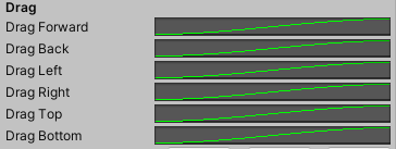
Scale6 is a function I wrote that is similar to Unity3D’s Vector3.Scale. For example, it multiplies the Z axis of the input (lv.normalized) with dragForward if Z is positive or dragBack if Z is negative. This allows us to specify different drag values for all 6 cardinal directions (so forward and backward can have different drag coefficients) and blend smoothly between them.
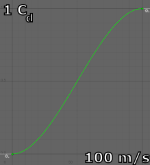
Actually, the 6 drag coefficients above are all controlled by Unity3D’s AnimationCurve class. The input for the curve is speed and the output is Cd. This allows us to fine tune the drag behavior at different speeds.
For example, I use the animation curve to reduce the effect of drag at low speed. The velocity squared term already does this, so the animation curve exaggerates this effect.
Lastly, the drag is increased when the player deploys airbrakes or flaps. These are simply extra drag values added to the forward drag direction. So the final function looks like this:
float airbrakeDrag = AirbrakeDeployed ? this.airbrakeDrag : 0;
float flapsDrag = FlapsDeployed ? this.flapsDrag : 0;

var coefficient = Utilities.Scale6(
    lv.normalized,
    dragRight.Evaluate(Mathf.Abs(lv.x)), dragLeft.Evaluate(Mathf.Abs(lv.x)),
    dragTop.Evaluate(Mathf.Abs(lv.y)), dragBottom.Evaluate(Mathf.Abs(lv.y)),
    dragForward.Evaluate(Mathf.Abs(lv.z)) + airbrakeDrag + flapsDrag,   //include extra drag for forward coefficient
    dragBack.Evaluate(Mathf.Abs(lv.z))
);
Lift and Induced Drag
This is the lift equation:
\(L=\frac12\times A\times\rho\times C_L\times v^2\)- L is the resulting lift force
- ρ (rho) is the air density
- v is the velocity
- A is the surface area
- CL is the coefficient of lift
Just like drag, we ignore air density and surface area, so the lift force is effectively velocity squared times the coefficient of lift. This coefficient is controlled by another AnimationCurve. However the input for this curve is AOA, not speed.
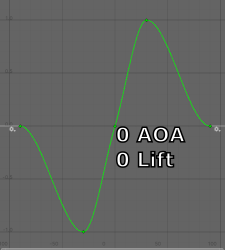
This curve takes input in degrees from -90 to 90. At 0 degrees AOA, the lift coefficient is 0. At 30 degrees AOA, the coefficient is 1 (the right peak). Going beyond 30 is the stall region, where the coefficient begins to drop off. This curve also handles negative AOA by producing a negative coefficient.
The lift from the above curve is multiplied by liftPower. This value does not correspond to any particular physical unit (as far as I know) and is just used to tune the amount of lift generated. For example, I use a liftPower of 150 for this project.
Induced drag depends on the same variables as lift, so we also calculate that in this function. This is the formula for induced drag:
\(C_{di}=\frac{C_L^2}{\pi\times AR\times e}\)- Cdi is the resulting induced drag
- CL is the coefficient of lift from earlier
- π, AR, and e are all constants
Induced drag varies based on the square of the coefficient of lift. We multiply by a hand tuned value which encompasses the constants above. This value is chosen by another AnimationCurve, which takes speed as input.
Altogether, the function for lift and induced drag looks like this:
Vector3 CalculateLift(float angleOfAttack, Vector3 rightAxis, float liftPower, AnimationCurve aoaCurve, AnimationCurve inducedDragCurve) {
    var liftVelocity = Vector3.ProjectOnPlane(LocalVelocity, rightAxis);    //project velocity onto YZ plane
    var v2 = liftVelocity.sqrMagnitude;                                     //square of velocity

    //lift = velocity^2 * coefficient * liftPower
    //coefficient varies with AOA
    var liftCoefficient = aoaCurve.Evaluate(angleOfAttack * Mathf.Rad2Deg);
    var liftForce = v2 * liftCoefficient * liftPower;

    //lift is perpendicular to velocity
    var liftDirection = Vector3.Cross(liftVelocity.normalized, rightAxis);
    var lift = liftDirection * liftForce;

    //induced drag varies with square of lift coefficient
    var dragForce = liftCoefficient * liftCoefficient;
    var dragDirection = -liftVelocity.normalized;
    var inducedDrag = dragDirection * v2 * dragForce * this.inducedDrag * inducedDragCurve.Evaluate(Mathf.Max(0, LocalVelocity.z));

    return lift + inducedDrag;
}
This function is used to provide the lift for the wings and vertical stabilizer. Wing lift is calculated using the parameters AngleOfAttack and Vector3.right to provide lift in the correct direction. The vertical stabilizers apply lift sideways, so it uses AngleOfAttackYaw and Vector3.up. The vertical stabilizers have their own lift power and animation curves.
I use the Vector3.ProjectOnPlane function to find the part of velocity that flows directly over the wings. The idea is that air flowing sideways over the wing produces no lift, so it’s ignored. Then the resulting lift force is applied perpendicular to the air flow and induced drag is applied opposite the air flow.
This CalculateLift function is called like this:
void UpdateLift() {
    float flapsLiftPower = FlapsDeployed ? this.flapsLiftPower : 0;
    float flapsAOABias = FlapsDeployed ? this.flapsAOABias : 0;

    var liftForce = CalculateLift(
        AngleOfAttack + (flapsAOABias * Mathf.Deg2Rad), Vector3.right,
        liftPower + flapsLiftPower,
        liftAOACurve,
        inducedDragCurve
    );

    var yawForce = CalculateLift(AngleOfAttackYaw, Vector3.up, rudderPower, rudderAOACurve, rudderInducedDragCurve);

    Rigidbody.AddRelativeForce(liftForce);
    Rigidbody.AddRelativeForce(yawForce);
}
FlapsDeployed is a bool property controlled by the player. The extra lift from flaps is implemented by increasing the lift power and AOA by arbitrary amounts. The player gets extra lift for takeoff by using flaps.
The lift generated by the vertical stabilizers is also applied in here. Note that this lift is just a stabilizing force, not a turning force. That is, this does not produce any torque.
Steering
In real life, the control surfaces on a plane create lift that torques the aircraft into a new orientation. The result of a control input can be quite complex. Changing the plane’s orientation will affect how all surfaces produce lift, even those that are in a neutral position.
For example, giving a yaw input is supposed to rotate the plane around the vertical axis. However, the rudder is located above the center of mass, so the lift force produced by the rudder will also create a slight roll. Small interactions like this can make the plane more difficult to fly.
The solution is to fake it. Since we aren’t simulating individual surfaces, we don’t have to worry about any input causing an unintended change. We simply apply a torque directly to the plane. This gives us a few control over a few things. For each axis, we can specify a turn rate in degrees / second and a turn acceleration rate in degrees / second / second. We get perfectly stable flight, so the plane only turns according to player input, and the plane stops turning when the player releases the input.
float CalculateSteering(float dt, float angularVelocity, float targetVelocity, float acceleration) {
    var error = targetVelocity - angularVelocity;
    var accel = acceleration * dt;
    return Mathf.Clamp(error, -accel, accel);
}
This function calculates the torque needed for a single axis to reach a target angular velocity. It calculates the torque needed to reach the target, which is limited by the plane’s turn acceleration, and avoids overshooting the target.
void UpdateSteering(float dt) {
    var speed = Mathf.Max(0, LocalVelocity.z);
    var steeringPower = steeringCurve.Evaluate(speed);

    var targetAV = Vector3.Scale(controlInput, turnSpeed * steeringPower);
    var av = LocalAngularVelocity * Mathf.Rad2Deg;

    var correction = new Vector3(
        CalculateSteering(dt, av.x, targetAV.x, turnAcceleration.x * steeringPower),
        CalculateSteering(dt, av.y, targetAV.y, turnAcceleration.y * steeringPower),
        CalculateSteering(dt, av.z, targetAV.z, turnAcceleration.z * steeringPower)
    );

    Rigidbody.AddRelativeTorque(correction * Mathf.Deg2Rad, ForceMode.VelocityChange);    //ignore rigidbody mass
}
Here we turn the player’s input into a target angular velocity. controlInput is the combination of inputs from the player: pitch, roll, and yaw. That is multiplied with the turn rate specified to get the target angular velocity, targetAV. The target angular velocity is limited by steeringPower, an animation curve that reduces the strength of the turn at low speeds. Then the torque is calculated for each axis and applied.
G Forces and G Force Limiter
The last system that we need to add is a G Limiter. But first, we need a way to estimate future G Forces. The plane can measure current G Forces just by tracking the last frame’s velocity. But we can’t measure future G Forces the same way.
Here is the function I use to estimate G Force:
Vector3 CalculateGForce(Vector3 angularVelocity, Vector3 velocity) {
    //estiamte G Force from angular velocity and velocity
    //Velocity = AngularVelocity * Radius
    //G = Velocity^2 / R
    //G = (Velocity * AngularVelocity * Radius) / Radius
    //G = Velocity * AngularVelocity
    //G = V cross A
    return Vector3.Cross(angularVelocity, velocity);
}
We can calculate G Force using velocity and angular velocity of the plane. The angular velocity is the turn rate we specified earlier.
Given the formula for tangential velocity of circular motion:
\(V\;=\;AV\;\times\:R\)- V is (tangential) velocity
- AV is angular velocity
- R is radius
and the formula for G Force of circular motion:
\(G\;=V^2/R\)- G is G Force
- V is (tangential) velocity
- R is radius
We can derive the above function:
\(G\;=V^2/R\\G\;=\;\;(V\times V)\;/\;R\\G\;=\;(V\times AV\times R)/R\\G\;=\;V\times AV\)G Force is velocity times angular velocity. Since our velocity and angular velocity are 3D vectors, I used cross product to multiply them. Don’t ask me why that works, because I don’t know. I discovered that by guessing.
We also need a way to determine the G Limit depending on the direction of the player’s input. Remember that a pitch down movement has a limit of -4G, while a pitch up movement can be 8G. We use the Scale6 function again to handle different limits depending on sign. This also blends between multiple axes smoothly. So pitching by itself will give a higher G Limit than pitching and rolling.
Vector3 CalculateGForceLimit(Vector3 input) {
    return Utilities.Scale6(input,
        gLimit, gLimitPitch,    //pitch down, pitch up
        gLimit, gLimit,         //yaw
        gLimit, gLimit          //roll
    ) * 9.81f;
}
Now with all of this, we can write the G Limiter function. If the plane (at the current speed) is capable of making a 16G turn and the limit is 8G, we multiply the player’s input by 0.5. If the plane is capable of only 4G but the limit is 8G, we do not change the player’s input.
The output of the G Limiter function is some value in the range [0, 1]. The G Limiter is “inactive” when it returns 1, and “active” when it returns something less than 1.
float CalculateGLimiter(Vector3 controlInput, Vector3 maxAngularVelocity) {
    //if the player gives input with magnitude less than 1, scale up their input so that magnitude == 1
    var maxInput = controlInput.normalized;

    var limit = CalculateGForceLimit(maxInput);
    var maxGForce = CalculateGForce(Vector3.Scale(maxInput, maxAngularVelocity), LocalVelocity);

    if (maxGForce.magnitude > limit.magnitude) {
        //example:
        //maxGForce = 16G, limit = 8G
        //so this is 8 / 16 or 0.5
        return limit.magnitude / maxGForce.magnitude;
    }

    return 1;
}
We calculate maxInput, which is the player’s input, scaled up so that the magnitude is equal to 1. Even if the player is giving 50% input, we scale it to 100% input. This is so we know what the maximum turn rate is in the direction specified by the player.
Otherwise the player may see the G Limiter activating at 50% input, limiting him to an 8G turn. And then when the player gives 100% input, the G Limiter is still active and the turn remains at 8G. In this situation, the space between 50% and 100% input would be wasted, which limits how precise the player can give input and feels bad.
We scale up the input and calculate the maximum turn rate so that the player hits 50% G limit at 50% input, and 100% G limit at 100% input.
Conclusion
Corner speed and energy management emerge by tuning the plane’s variables. You can control the strength of a turn at low speed by adjusting steeringCurve. You can control the strength of a turn at high speed by adjusting the G Limiter. You can control energy gain and loss by adjusting maxThrust and the induced drag variables inducedDrag and inducedDragCurve.
With all of this, we have created a plane that respects the concepts of flight described above. You can try out the plane at the Github repo. The tag part-1 is the progress up to this point.
The next few parts will cover the HUD, weapons, and AI.