This is the fourth part of my flight sim series. You can read the first three parts here, one, two, and three. These cover basic flight simulation, HUD, and combat AI respectively.
This article will discuss creating an autopilot system for the flight simulator. The AI created in part 3 only handles combat. For non combat tasks, a different approach must be taken. We will create an autopilot system very similar in behavior to a real plane’s autopilot.
This might seem like a daunting task. But if you can fly a plane manually, every part of the autopilot is understandable and achievable. You already know every behavior needed to fly the plane, you just need to translate it into code. Writing automated systems like this isn’t limited to planes. If you can describe the behavior numerically, you can write an autopilot system for it.
Note that in this project, the autopilot and the combat AI are mutually exclusive. You cannot activate both or switch between them at runtime. A more robust demo would have these in the same system, but 🤷♂️.
This build can be played in browser or downloaded at itch.io.
Source code is available at Github at tag part-4
Table of Contents
Implementation
There are three modes for this autopilot system: Takeoff, Navigation, and Landing.
The autopilot system relies heavily on PID controllers. You can read my previous post about PIDs here: PID Controllers in Unity3D. Many more PID controllers will be added and tuned to make the autopilot work.
Recall that a PID controller works by measuring the difference between a target value and the current value. This difference is called error. The error is used to calculate an output value, which is used to control the system. As we will see in this article, PIDs can be very flexible. There’s no restriction on what the input and output values are.
Speed Hold
A simple usage of PID control is controlling the speed of the plane. The plane’s current speed and acceleration are used as the value and velocity of the PID.
void SetThrottleSpeedHold(float dt, float targetSpeed) {
    var speed = plane.LocalVelocity.z * Units.metersToKnots;
    var accel = plane.LocalGForce.z * Units.metersToKnots;

    var throttleInput = speedHoldController.Update(dt, speed, targetSpeed, accel);
    plane.SetThrottleInput(throttleInput);
}
Note that the input units for the PID controller are in knots. The internal state of the plane is measured in meters per second, so a simple conversion is needed. Using aeronautical units for this lets the PID designer work with numbers that are more sensible for aviation.
There is no strong reason to use knots, meters per second, kilometers per hour, or any other unit for PID design. I used knots because I have a stronger intuitive sense for airspeed in knots than in other units. The system you design can use whatever units make the most sense to you. Document which unit is used for which input and be careful not to end up in a system with a confusing mixture of units.
This speed controller is used almost everywhere. It can reach any speed the plane needs during takeoff, navigation and landing. This controller can automatically use the afterburner and airbrake just by setting the throttle input.
It would be theoretically better to have a separate speed controller for landing and takeoff. During landing and takeoff, the plane’s flaps would be deployed which greatly increases drag. A different PID could be tuned for more precise control over speed. However, a single speed controller for all parts of flight is good enough, so this is left as an exercise for the reader.
Basic Control Logic
A few functions for roll, pitch, and yaw control can be written as basic building blocks for the rest of the autopilot system. These functions simply hold the plane at a specific angle. The way they work should be obvious if you are familiar with PID controllers.
The pitch controller:
float CalculatePitchHold(float dt, float targetPitch) {
    var pitch = plane.PitchYawRoll.x;
    var pitchRate = GetPitchRate(plane);
    var pitchInput = pitchHoldController.Update(dt, pitch, targetPitch, pitchRate);
    return pitchInput;
}
The roll controller:
float CalculateRollHold(float dt, float targetRoll) {
    var roll = plane.PitchYawRoll.z;
    var rollRate = GetRollRate(plane);
    var rollInput = rollController.Update(dt, roll, targetRoll, rollRate);
    return rollInput;
}
The yaw controller:
float CalculateYawHeading(float dt, float heading, float targetHeading) {
    var yawRate = GetYawRate(plane);
    var yawInput = yawHeadingController.Update(dt, heading, targetHeading, yawRate);
    return yawInput;
}
ValueVelocity
A utility struct used in a few places is called ValueVelocity. This struct allows you to track the velocity of a float variable over time. It needs to be updated through the Update method, which includes the timestep for calculating velocity. It gives a default value of 0 for both the value and velocity if it has not been updated enough times, which is generally fine for PID controllers.
This is needed for a handful of measurements where a “velocity” is not readily available.
For example, this allows you to measure altitude as the “value” and altitude velocity (or climb rate) as the “velocity”.
struct ValueVelocity {
    float value;
    float velocity;
    bool hasValue;

    public void Update(float dt, float newValue) {
        if (hasValue && dt != 0) {
            velocity = (newValue - value) / dt;
        } else {
            velocity = 0;
        }

        value = newValue;
    }

    public void Reset() {
        value = 0;
        velocity = 0;
        hasValue = false;
    }
}
Takeoff
Takeoff is the easiest behavior to implement. Broadly speaking, you just set the throttle to max and pull up once you reach takeoff speed. Once you get enough speed and altitude, you transition to Navigation mode. Easy!
While takeoff is simple, there are still some subtly different behaviors that you need to do at different stages of takeoff. To handle this, we add a simple state machine to handle the different behaviors.
The zeroth state is called “Idle”. The plane does nothing in this state. Push the “Takeoff” button to start the takeoff.
The first state is called “Start Takeoff”. The autopilot sets the throttle to max and waits while the plane accelerates. Once the plane reaches the rotation speed, we transition to the next state.
The second state is called “Rotation”. Rotation is when you begin pulling back on the stick to raise the nose of the aircraft. Once the aircraft gains enough speed to lift off of the ground, we transition to the next state.
On real aircraft, rotation can occur well below takeoff speed. So the plane will pitch up and the rear wheels will remain on the ground. The aircraft holds a higher Angle of Attack than if the nose was on the ground, increasing the amount of lift generated. As the plane continues to accelerate, it will eventually generate enough lift to take off.
The third and final state is called “Finish Takeoff”. While the plane is already in the air, we still want it to gain more speed and altitude. So the plane simply continues climbing until it reaches a certain altitude above the runway and a certain speed. Once we reach a safe value for both of these, we transition out of Takeoff mode and into Navigation mode.
Real aircraft also need to deal with the possibility of aborting a takeoff. While below a certain speed, a plane can abort takeoff by cutting throttle and applying maximum braking. This speed is called V1. If a problem occurs above this speed, the pilot must commit to taking off.
This decision is made mostly based on whether some mechanical failure occurs during takeoff. Since failures are not modeled in this project, there is never any reason to abort takeoff. So no state is needed to handle the abort case.
The code for the takeoff behavior is quite simple. We have a state machine with three states.
void HandleTakeoff(float dt) {
    switch (takeoffMode.state) {
        case TakeoffState.StartTakeoff:
            HandleStartTakeoff(dt);
            break;
        case TakeoffState.Rotate:
            HandleRotateTakeoff(dt);
            break;
        case TakeoffState.FinishTakeoff:
            HandleFinishTakeoff(dt);
            break;
    }
}
Each state handles the control logic and then checks if the state machine should be transitioned.
The Start Takeoff state:
void HandleStartTakeoff(float dt) {
    plane.SetThrottleInput(1);

    var pitchInput = CalculatePitchHold(dt, 0);
    var rollInput = CalculateRollHold(dt, 0);

    var steering = new Vector3(pitchInput, 0, rollInput);
    SetControlInput(plane, steering);

    var speedTarget = takeoffMode.rotationSpeedKts / Units.metersToKnots;

    if (plane.LocalVelocity.z > speedTarget) {
        takeoffMode.state = TakeoffModeState.TakeoffState.Rotate;
    }
}
The throttle is set to 1, maximum throttle. Pitch and roll use the PID functions to hold the plane level. There shouldn’t be any forces that cause the plane to pitch or roll right now. But if there are, the PID controller will try to bring the plane back to level. Yaw input is 0.
This function transitions to the next state when the plane reaches the rotation speed.
The Rotate Takeoff state:
void HandleRotateTakeoff(float dt) {
    plane.SetThrottleInput(1);

    var pitchInput = CalculatePitchHold(dt, takeoffMode.rotationAngle);
    var rollInput = CalculateRollHold(dt, 0);

    var steering = new Vector3(pitchInput, 0, rollInput);
    SetControlInput(plane, steering);

    if (!plane.Grounded) {
        takeoffMode.state = TakeoffModeState.TakeoffState.FinishTakeoff;
    }
}
The autopilot gives a pitch input to reach the rotation angle. Because the plane’s speed is still below the takeoff speed, we cannot control Angle of Attack. The plane will be stuck on the ground and “flying” level regardless of pitch input. We can only pitch the aircraft and wait for the speed to increase.
This function transitions to the next state once the plane’s wheels are off the ground.
And the Finish Takeoff state:
void HandleFinishTakeoff(float dt) {
    SetThrottleSpeedHold(dt, takeoffMode.takeoffTargetSpeedKts);

    var pitchInput = CalculateNavigateClimbRateMode(dt, takeoffMode.finishTakeoffClimbRateFtPerMin);
    var rollInput = CalculateRollHold(dt, 0);

    var steering = new Vector3(pitchInput, 0, rollInput);
    SetControlInput(plane, steering);

    var alt = plane.Rigidbody.position.y * Units.metersToFeet;
    var targetAlt = takeoffMode.finishTakeoffMinFtAGL + takeoffMode.runwayAltitude;
    var speed = plane.LocalVelocity.z * Units.metersToKnots;

    if (alt >= targetAlt && speed >= takeoffMode.finishTakeoffMinSpeedKts) {
        EnterNavigateMode();
    }
}
Once the plane is airborne, we can control the pitch using the climb-rate controller (described below). The throttle can be reduced from maximum.
This function transitions to Navigation mode once the plane is at a safe speed and altitude.
Navigation is more complex to implement. The previous part in this series covers implementing a combat AI that can fly the plane in three dimensions while pursuing a target. A navigation autopilot does not need to fly the plane as aggressively. It only needs to handle altitude control and turning.
The simplest case is to fly the aircraft straight and level. We already have the controllers for roll and speed. Pitch control requires a few new PID controllers. This is more complicated than the pitch controller described above.
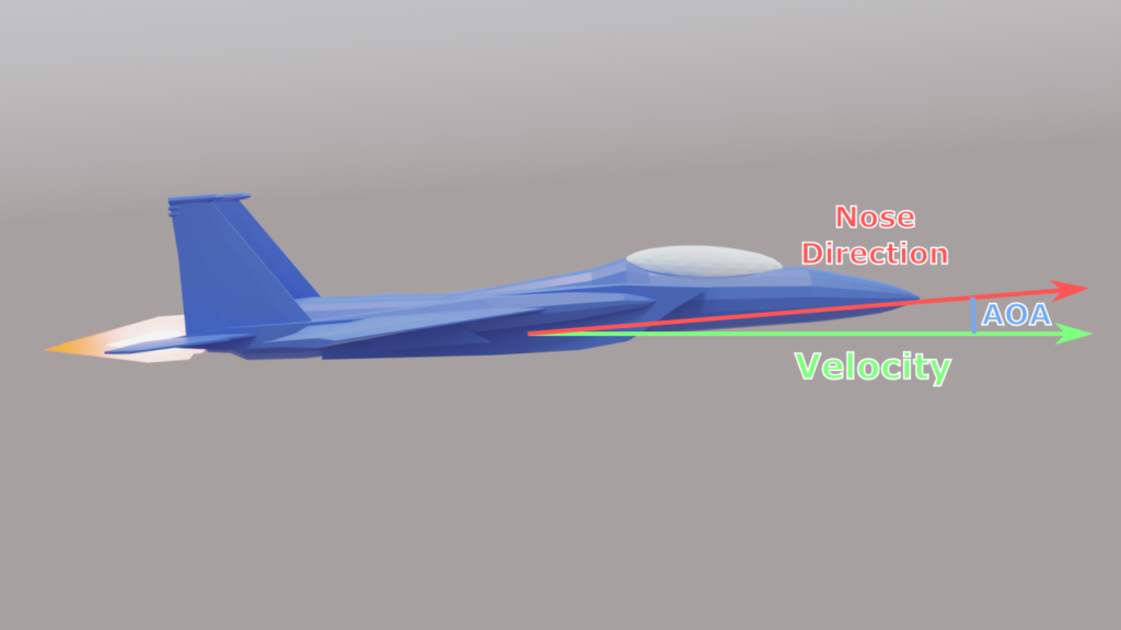
Recall that an aircraft needs to maintain some non-zero Angle of Attack to produce lift. This is visualized by the velocity indicator and the boresight indicator on the HUD. To maintain level flight, the plane’s nose will be pointed slightly upwards while the velocity indicator is held level. How much AOA is needed depends on the plane’s speed. At lower speeds, the plane needs a higher AOA to produce the same amount of lift.
Holding the aircraft’s pitch at zero is not correct. This would result in a slight downwards velocity as the plane cannot maintain level flight with zero AOA and zero lift. The autopilot needs to find the correct pitch angle to match the AOA required.
Instead, the autopilot needs to hold the velocity vector level. Specifically it needs to hold the vertical component of the velocity vector at zero. The vertical component of velocity is called the climb rate. In Unity, it’s the Y axis. By looking at this component only, we can measure how fast the aircraft is changing altitude.
Cascaded PID Controllers
It may be possible to control the pitch axis of the joystick directly based on climb rate. But this would be finicky, since the required AOA changes with speed. Instead the pitch controller takes a target angle and the plane’s current angle to generate a joystick input. The target input of the pitch controller can be generated by a different PID controller in a cascade. A cascaded PID controller is when the output of one PID controller is used as the target of another PID controller.
So another PID controller is added which measures the plane’s vertical velocity and generates a target pitch. We call this the climb-rate controller. If we tune the climb-rate controller correctly, it will automatically find the correct pitch angle, which is then passed to the pitch controller.
These two PID controllers work together in a larger feedback loop to automatically hold the plane’s vertical velocity at zero. This can work over a large range of speeds. The I term must be used in this controller. The I term will settle at different values as the climb-rate controller “discovers” the correct AOA to hold.
If we set the target vertical velocity of the climb-rate controller to a value other than zero, the aircraft can hold a steady climb rate of, for example, 1000 feet per minute. So not only can it fly straight and level, it can also smoothly change altitude.
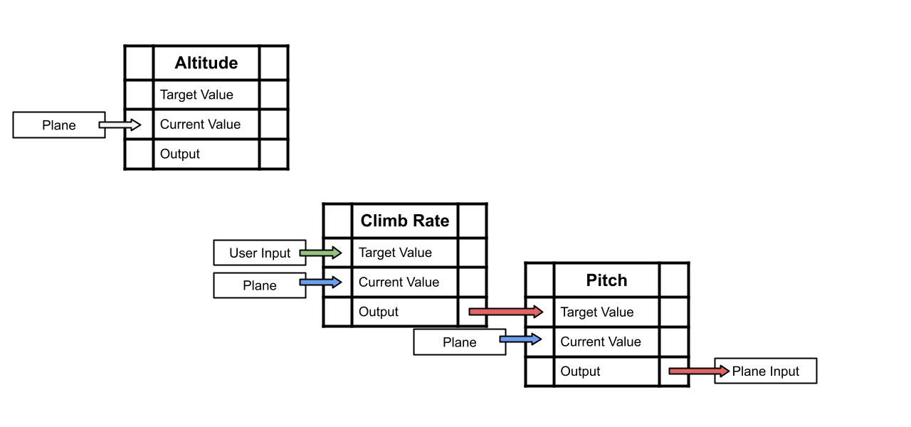
Another cascade can be added above this to set the target vertical velocity. We call this the altitude controller. By measuring the plane’s current altitude, it can generate a target climb rate. The climb rate will reduce as it approaches the target altitude. Then the pitch controller will hold the plane at level flight once the climb rate is reduced to zero.

There’s no theoretical limit to how many cascades can be added to a control system. It’s only limited by how many variables you can measure and how many controllers you can tune. The downside is, by adding more controllers, you add more places where the control system can oscillate. For example, the altitude controller may be tuned poorly, so the climb rate oscillates. Or the climb-rate controller may be tuned poorly, so the pitch angle oscillates, etc.
More cascades means the feedback loop takes longer to resolve. Generally, that means that the control system designer needs to use smaller coefficients to create more gentle control inputs. But poor tuning in one level can cause an unintended correction in another level, causing an uncontrollable feedback loop. It’s best to tune the levels from the bottom up.
The min and max output values of each PID controller can limit how large the input given to the next controller is. So even with a large difference in altitude, the altitude controller will only output a target climb rate of +/- 6000 feet per minute, for example.
An additional benefit of cascaded PID controllers is that we can skip the “early” controllers and just set a controller’s target directly. Our system currently has three controllers: altitude, climb rate, and pitch. We can control altitude by setting the target for the altitude controller. But we can bypass it and set a target climb rate directly. Then our system would try to maintain a steady climb rate without stopping at any particular altitude.
We can add different pitch control modes by skipping the altitude or climb-rate controller. This gives us a more flexible control system.
Banking
In the combat AI, the plane is turned by rolling and then pitching. This is good for combat situations where aggressive maneuvering is needed to win a dogfight. But for simple navigation, a banking turn is better.
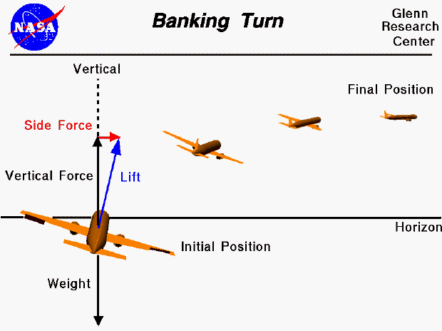
A banking turn is when an aircraft changes it’s heading by rolling to one side. By rolling, the lift generated by the wings no longer points straight up, so the aircraft is pulled into a new direction. This creates a gentle turning motion and is the way aircraft turn most of the time. If you’ve ever been on an airliner, you might see the plane bank by 30 degrees during the landing approach.
A crucial part of a banking turn is keeping the aircraft coordinated. This means using the rudder to keep the plane aligned with the airflow. More specifically, it means keeping the Angle of Slip (or AOS) as close to zero as possible. Angle of Slip is like Angle of Attack, but measured on the yaw axis.
Note that while the rudder is part of a banking turn, the rudder is not turning the aircraft. It is technically possible to use the rudder alone to turn, but this is not really useful. The angled lift vector is what causes the turn.
Unfortunately, the flight model in this simulator does not accurately model banking behavior. If you try to bank, the plane will simply continue flying straight. This is due to the lack of stability simulation. Stability is the force that pulls the plane’s nose vector towards the plane’s velocity vector. This would naturally pull the plane’s nose sideways to reduce the AOS. The rudder would simply push the nose a little bit further to bring AOS to zero.
Since there is no stability force, we must use the rudder more. While this does mean applying rudder in the direction of the turn, the rudder is still not turning the plane. It is only used to keep the plane coordinated.
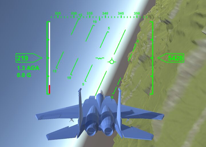
Notice how the velocity indicator is significantly to the right of the boresight indicator. This means there is a large Angle of Slip on the aircraft.
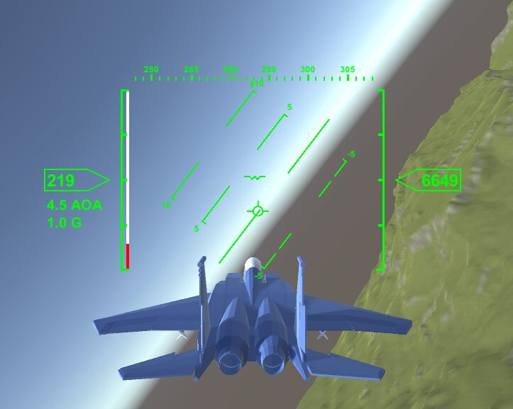
In a coordinated turn, the velocity indicator is now directly below the boresight.
Flying a coordinated turn is a basic maneuver that every pilot must learn. For an autopilot, a few PID controllers are needed. We add a yaw-slip controller, which has the job of reducing the AOS to zero. To roll the aircraft, we use the existing roll controller. But the target for the roll controller is calculated by the new turn-bank controller.
To make a level banking turn, the turn-bank controller will take in the target heading and current heading, and calculate a roll angle. The roll controller will maintain that roll angle. The yaw-slip controller will apply yaw inputs to reduce AOS to zero. The climb-rate controller and pitch controller will apply pitch inputs to maintain level flight. This will slowly turn the aircraft towards the target heading while maintaining altitude.
A banking turn is more complicated than the roll-and-pull method used in the combat AI. But the result is a much gentler turn, in terms of G-force on the plane, and minimal loss of energy. This is why banking turns are used by all aircraft for basic maneuvering, even fighter jets.
Altitude control and bank turns are the two main elements we need to make a Navigation mode for our autopilot. Every navigation related task can be accomplished by enabling some or all of the cascade levels of these controllers. We can give the pilot more control over the autopilot by allowing them to configure which cascades are being used.
While the Takeoff and Landing modes use state machines to move between states, Navigation mode is simpler. The mode is simply selected by the user. There is no automatic mode transition.
As mentioned above, there are separate uses for an altitude controller, a climb rate controller, and a pitch controller. These modes are simply different levels of the cascaded PID controller.
The pitch mode is trivial to implement. This behavior only holds the plane at the target pitch. This simply calls the CalculatePitchHold function described above.
float CalculateNavigatePitchHoldMode(float dt, float targetPitch) {
    return CalculatePitchHold(dt, targetPitch);
}
The climb rate mode calculates the target pitch by calling the climb-rate controller. Then it calls CalculateNavigatePitchHoldMode.
float CalculateNavigateClimbRateMode(float dt, float targetClimbRate) {
    // convert m/s to ft/min
    var verticalSpeedFt = plane.Rigidbody.velocity.y * Units.metersToFeet * 60;
    var verticalAccelFt = plane.GForce.y * Units.metersToFeet * 60;

    var pitchTarget = climbRateController.Update(dt, verticalSpeedFt, targetClimbRate, verticalAccelFt);
    var pitchInput = CalculateNavigatePitchHoldMode(dt, pitchTarget);

    return pitchInput;
}
The altitude mode calculates the target climb rate by calling the altitude controller. Then it calls CalculateNavigateClimbRateMode.
float CalculateNavigateAltitudeHoldMode(float dt, float targetAltitudeFt) {
    // convert m to ft, m/s to ft/min
    var altitudeFt = plane.Rigidbody.position.y * Units.metersToFeet;
    var verticalSpeedFt = plane.Rigidbody.velocity.y * Units.metersToFeet * 60;

    var targetClimbRate = altitudeHoldController.Update(dt, altitudeFt, targetAltitudeFt, verticalSpeedFt);
    var pitchInput = CalculateNavigateClimbRateMode(dt, targetClimbRate);

    return pitchInput;
}
It really is that simple.
These modes form a cascaded PID controller. Each mode calculates a target and passes that to the mode below it. We have a separate function for each mode to allow us to skip a particular level of cascade.
Another mode that is useful to add is a “flight path mode”. In autopilot systems, the direction of the velocity vector is called the flight path. Specifically, flight path is the angle of the velocity velocity above the horizon. Flight path is measured in degrees. In some cases, it is more useful to control the flight path instead of the pitch angle. This would allow the autopilot to hold a 5 degree climb regardless of speed, for example.
Both pitch and flight path mode are necessary because they handle different situations. For example, during takeoff, a pitch mode controller is more useful because the autopilot simply holds the nose at a specific pitch angle. Flight path mode would not be useful because the flight path will remain level while the plane is below takeoff speed and no amount of pitch input will change that. Thus a flight path mode would be useless.
But a flight path mode would be more useful for following a predetermined path of nodes. These nodes may have variable altitude to avoid terrain features like hills. Pitch mode would not account for the difference between nose vector and velocity vector, so the aircraft may take a flight path that is dangerously close to the terrain. A flight path mode would be more useful because the autopilot would follow a specific path in 3D space, regardless of the plane’s current speed.
We can measure the flight path angle by performing some simple math. Flight path angle means the angle of the velocity vector above or below the horizon, ignoring roll and yaw.
We can measure the flight path by calculating the angle between the velocity vector and the world vertical axis.
var velocityDir = plane.Rigidbody.velocity.normalized;
var currentFlightPath = 90 - Vector3.Angle(Vector3.up, velocityDir);
This gives a flight path of 0 when the velocity vector is on the horizon and 90 when it’s pointed straight up.
Now, adding a function for flight path control is simple.
float CalculateFlightPathHold(float dt, float pitchTarget, float pitch, float pitchRate) {
    var pitchInput = pitchHoldController.Update(dt, pitch, pitchTarget, pitchRate);

    return pitchInput;
}
This function just uses CalculatePitchHold with no modifications to the input. This may seem strange, but flight path control is not significantly different from pitch control. Either way, we need to control the elevator input to correct a small pitch error. The input and target values are measured differently, but behavior of the PID controller would not be different. Thus we can simply reuse the existing pitch controller.
This is not a cascade level like the other controllers. The flight path controller is operating on different input. But the input space is still measured in degrees. The output space is the joystick input in both cases. So no change needs to be made and the existing pitch controller can be reused.
There are complications with the flight path controller interacting with banking. If the user wants to change heading and flight path simultaneously, the autopilot’s control inputs start interfering with each other.
Imagine the user wants to turn right and descend to a flight path of -5 degrees. The autopilot will roll the plane right (to turn) and then pitch down (to change the flight path). The pitch down will cause the plane’s heading to change to the left, even though the user wants to turn right.
We can fix this by pitching first, and then rolling. All of the pitch modes in navigation provide feedback on whether the current pitch is close enough to the target pitch, however that target pitch is generated.
This is done by adding an out parameter to the pitch mode functions.
float CalculateNavigatePitchHoldMode(float dt, float targetPitch, out bool applyTurn) {
    currentTargetPitch = targetPitch;

    // apply turn only if pitch is within a safe threshold
    var pitch = plane.PitchYawRoll.x;
    applyTurn = (Mathf.Abs(targetPitch - pitch) < bankPitchThreshold);

    return CalculatePitchHold(dt, targetPitch);
}
The parameter applyTurn is set to true when the pitch error is small. The navigation mode disables banking until this is true. The cascaded functions simply pass the same out parameter to the bottom of the call chain. The applyTurn parameter is only set by CalculateNavigatePitchHoldMode and CalculateNavigateFlightPathMode. (Flight path mode isn’t part of the cascade)
With these 4 modes, the top level navigation mode can be implemented.
void HandleNavigateNormal(float dt) {
    SetThrottleSpeedHold(dt, navigateMode.targetSpeedKts);

    var yawRate = GetYawRate(plane);
    var targetHeading = navigateMode.targetHeading;

    var pitchInput = CalculateNavigatePitchControl(dt, out bool applyTurn);

    if (!applyTurn) {
        // ignore heading error until pitch is within threshold
        targetHeading = currentHeading;
    }

    var rollInput = CalculateRollBank(dt, targetHeading);
    var yawInput = CalculateYawSlip(dt, 0, yawRate);

    var steering = new Vector3(pitchInput, yawInput, rollInput);
    SetControlInput(plane, steering);
}
This function calculates the pitch, roll, yaw, and throttle for the plane. Roll and yaw use the bank and slip calculations discussed earlier. The pitch depends on which pitch mode is selected in a simple switch statement.
float CalculateNavigatePitchControl(float dt, out bool applyTurn) {
    float pitchInput = 0;

    switch (navigateMode.pitchControlMode) {
        default:
            applyTurn = false;
            break;
        case NavigateModeState.PitchControlMode.PitchMode:
            pitchInput = CalculateNavigatePitchHoldMode(dt, navigateMode.targetPitch, out applyTurn);
            break;
        case NavigateModeState.PitchControlMode.FlightPathMode:
            pitchInput = CalculateNavigateFlightPathMode(dt, navigateMode.targetPitch, out applyTurn);
            break;
        case NavigateModeState.PitchControlMode.AltitudeHoldMode:
            pitchInput = CalculateNavigateAltitudeHoldMode(dt, navigateMode.targetAltitudeFt, out applyTurn);
            break;
        case NavigateModeState.PitchControlMode.ClimbRateHold:
            pitchInput = CalculateNavigateClimbRateMode(dt, navigateMode.targetClimbRateFtPerMin, out applyTurn);
            break;
    }

    return pitchInput;
}
The pitchControlMode setting allows the user to select which level of the cascaded pitch controller to use, or to use flight path mode.
The autopilot can now control pitch and bank, which is all that is needed for the Navigation mode.
Waypoints
One final mode that is useful for navigation is waypoint following. In this mode, the plane will automatically fly towards a 3D waypoint. When it reaches the waypoint, it will begin flying to the next waypoint in the list. The autopilot will use the navigation behaviors above to fly towards the waypoints.
The waypoint system itself is rather simple. A WaypointList holds multiple Waypoints. The Navigation mode flies to each waypoint in the list. This Waypoint system can be used for any scripted or generated path the AI needs to follow.
The code for this is quite simple since we already have the functions from the normal Navigation mode.
void HandleNavigateWaypoint(float dt) {
    var targetPosition = navigateMode.waypointState.CurrentPosition;
    var error = targetPosition - currentPosition;
    var direction = error.normalized;
    var error2D = new Vector3(error.x, 0, error.z);
    var direction2D = error2D.normalized;

    var cross = Vector3.Cross(direction2D, Vector3.up);

    navigateMode.targetHeading = Vector3.SignedAngle(Vector3.forward, direction2D, Vector3.up);
    navigateMode.targetPitch = Vector3.SignedAngle(direction2D, direction, cross);

    ...
}
This function calculates the compass heading and flight path angle towards the waypoint. These values are then passed to the existing functions for flight path and bank turns. Essentially, this automatically updates the target heading and target flight path.
void HandleNavigateWaypoint(float dt) {
    ...

    SetThrottleSpeedHold(dt, navigateMode.targetSpeedKts);

    var yawRate = GetYawRate(plane);

    var pitchInput = CalculatePitchFlightPathMode(dt, currentFlightPath.Value, navigateMode.targetPitch, currentFlightPath.Velocity);
    var rollInput = CalculateRollBank(dt, Utilities.MapAngleTo180(navigateMode.targetHeading));
    var yawInput = CalculateYawSlip(dt, 0, yawRate);

    var steering = new Vector3(pitchInput, yawInput, rollInput);
    SetControlInput(plane, steering);
}
The implementation is almost trivial because we already have all of the navigation functions we need.
Landing
Landing is by far the most complex mode of the autopilot. The autopilot needs to align the aircraft with the runway from a large range of starting positions. Then the autopilot has to control the plane’s altitude and descent rate to maintain a good glide slope. Just before touchdown, the autopilot needs to “flare” the aircraft by pitching up and slowing the descent. After touchdown, it slows down the plane to complete stop.
Taking off is simple since the plane is already aligned with the runway and just needs to move in a straight line. Landing is complicated because the plane may start from any position and has to move to a single, precise area.
But what is a glide slope? Let’s start by defining all of the different measurements needed to land a plane and why they matter.
The first measurement is compass heading. The plane must be moving parallel to the runway. The heading controller from the navigation mode is sufficient to control this. But there is another problem. While the plane may be parallel to the runway, it also needs to be positioned in line with the runway. If it is too far to the left or right, the plane can’t land on the runway. If it is too far in front of or beyond the runway, it also cannot land.
The normal method for measuring positional error is called euclidean distance. This is simply the distance between two points. This is a basic calculation in any 3D game. Euclidean distance is always non-negative.
float distance = (pointA - pointB).magnitude;
float distance2 = Vector3.Distance(pointA, pointB);
Euclidean distance is not useful here. We want to drive more PID controllers, which requires a signed error measurement. And we need two measurements, forward along the runway and sideways across it. The forward error is called track error and the sideways error is called cross track error. If the runway had no rotation in world space, then we could find the track and cross track errors by simply reading the X and Z axes of the positional error. But if the runway is rotated at all, we can’t use this method.
Dot Products
The solution is to use a dot product to calculate the track and cross track errors. You may be familiar with dot products from the common game dev use of comparing directions.
float dot = Vector3.Dot(forwardDirection, direction);
This will return 1 if the two inputs are pointing in the exact same direction, -1 if they are pointing in exact opposite directions, and 0 if they are perpendicular. Comparing directions is the most common use of dot products, but far from the only one.
There’s no requirement that both inputs must be a direction. A more rigorous definition is that the dot product multiplies the length of the two vectors with the cosine of the angle between them. We can define a dot product like this, in pseudocode:
float Dot(Vector3 A, Vector3 B) {
    float dot = length(A) * length(B) * cosine(angle(A, B));
    return dot;
}
When A and B are both directions with length 1, then the value returned is solely the cosine of the angle between them. Thus the dot product returns 1 for aligned directions, cos(0), and -1 for opposite directions, cos(180).
More broadly, a dot product can be used to calculate the components of a vector in a new vector space. We already know how to calculate the track and cross track errors for a runway with no rotation. For a runway with rotation, we need to calculate the equivalent of the X and Z axes in the rotated vector space. The dot product is used to calculate this.
We need the plane’s positional error, the runway’s forward direction, and the runway’s sideways direction.
Vector3 error = (runwayPosition - planePosition);
Vector3 forward = runway.Forward;
Vector3 right = runway.Right;
float trackError = Vector3.Dot(error, -forward);
float crossTrackError = Vector3.Dot(error, right);
Note the minus sign in the call for trackError. The track error starts as a large, positive number. It decreases towards zero as the plane approaches the threshold of the runway. It becomes negative once the plane continues beyond the threshold. This is merely convention. This creates a positive number that shrinks as you approach the runway, which I find more intuitive.
Cross track error is the positional error of the plane relative to the runway’s centerline. In other words, it measures how left-or-right the plane is. When the plane is perfectly aligned, cross track error is zero. Cross track is negative on the left and positive on the right.
Because these values are signed, they can be used as the input for a PID controller (unlike euclidean distance).
Cross Track Error
To land the plane, we need to align it with the runway. From the navigation mode, we already have controllers that can align the plane to a specific heading. We also know the direction of the runway, but this is not sufficient for landing the plane. There may be a case where the plane is perfectly aligned with the runway direction (the heading error is zero), but the cross track error is large enough to miss the runway. In the ideal case, we would have a cross track error of zero and a heading error of zero.
We have a measurement for cross track error. Now we need to reduce it to zero while also reducing heading error to zero.
The solution is to use the heading controller that already exists and the known runway direction. Instead of aligning to the runway heading, we calculate a heading that reduces cross track to zero. This is done by adding a small bias, say 10 degrees, to the runway heading. As cross track error approaches zero, this bias also approaches zero.
This can be calculated by adding another PID controller. The input is cross track error in meters, the output is heading bias in degrees.
float CalculateCrossTrackTarget(float dt, float targetHeading, float crossTrackError, float crossTrackVelocity) {
    float bias = crossTrackController.Update(dt, crossTrackError, 0, crossTrackVelocity);
    return targetHeading + bias;
}
The output of this function is the heading that will bring the aircraft closer to the centerline of the runway. This value is passed to the existing turn-bank controller.
var targetHeading = CalculateCrossTrackTarget(dt, landingHeading, landingCrossTrack.Value, landingCrossTrack.Velocity);
var rollInput = CalculateRollBank(dt, targetHeading);
Note that landingCrossTrack is an instance of the ValueVelocity class defined earlier. This calculates the cross track velocity, so the D term of the PID controller can be used.
This controller means the autopilot will now reduce the cross track error and heading error to zero at the same time.
Glide Slope
The glide slope is the angle of the path between the aircraft and the touchdown zone of the runway. Imagine a straight line between the plane and runway. The angle between this line and the ground is the glide slope. A glide slope of 0 degrees means you are level with the runway. A glide slope of 90 means you are directly above the runway. Note that glide slope is measured in degrees below the horizon, while flight path is degrees above the horizon.
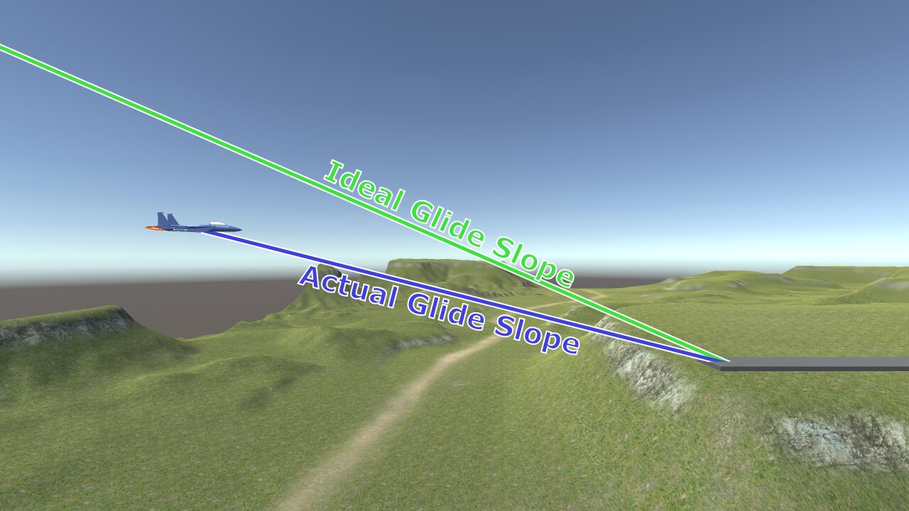
The ideal glide slope is about 3 degrees. The pilot lines up the velocity vector of the aircraft with this ideal glide slope. This means the velocity indicator on the HUD is 3 degrees below the horizon and pointing at the touchdown zone. This places the aircraft on a slow, controlled descent. Then the plane will eventually contact the runway in the touchdown zone.
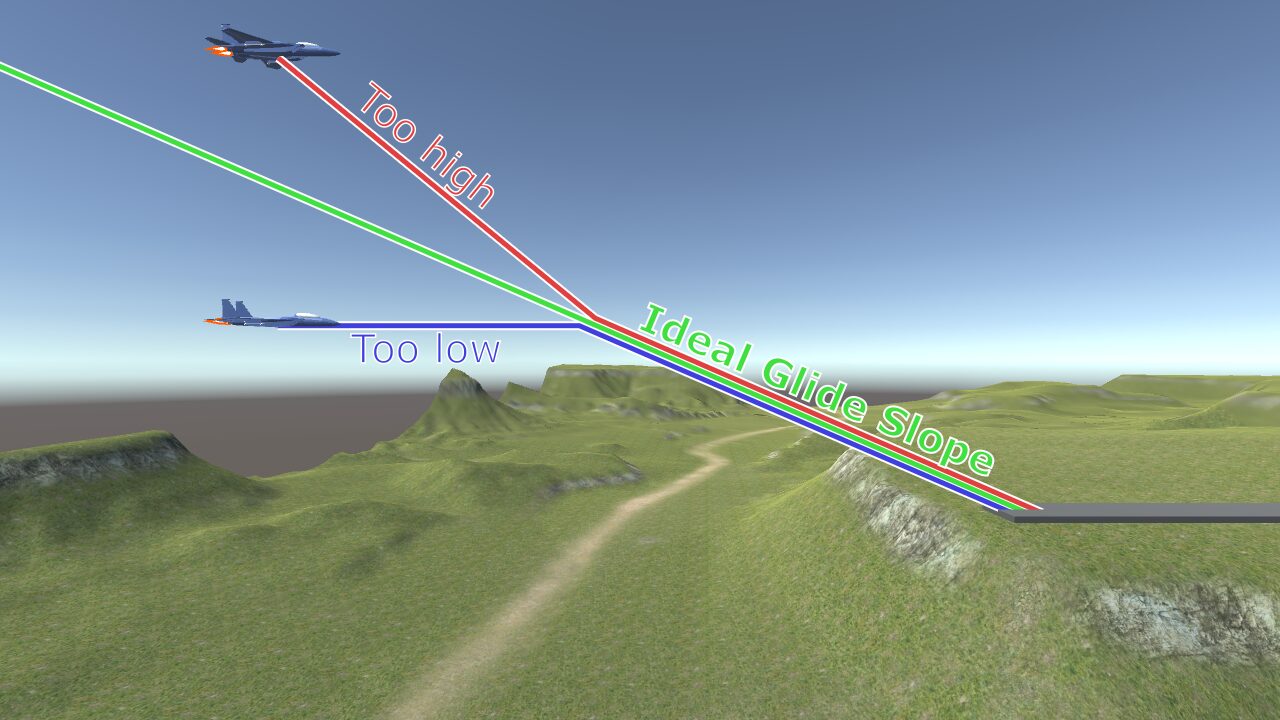
If the plane is not already lined up with the glide slope, the pilot must “intercept” the glide slope. That means adjusting the flight path until it matches the ideal glide slope. If the plane is “below” the glide slope, the pilot simply continues flying level until they intercept. If the plane is above the glide slope, the pilot must make a faster descent and then level out to match the glide slope.
Generally, it’s better to be below the glide slope, to avoid a rapid descent. But being too low also places you at risk of hitting something like a hill or building on the approach path.
Following a glide slope is the perfect use case for the flight path mode described above. We can measure the error between ideal glide slope and actual glide slope to produce a target flight path angle. This is implemented as another PID level above the flight path controller. If the plane is above the glide slope, this controller will calculate a target flight path that descends to intercept the glide slope. If the plane is below, it will calculate a flight path that is horizontal or even ascending.
The first step is to measure the glide slope. We calculate the direction from the plane to the touchdown zone of the runway:
var error = (touchdownPosition - planePosition);
var glideDirection = error.normalized;
This is passed as the “glideDirection” parameter to the function below:
float CalculateGlideSlope(Vector3 runwayDirection, Vector3 glideDirection) {
    Vector3 axis = Vector3.Cross(runwayDirection, Vector3.down);
    Vector3 runwayDir = Vector3.ProjectOnPlane(runwayDirection, axis);
    Vector3 glideDir = Vector3.ProjectOnPlane(glideDirection, axis);

    return Vector3.SignedAngle(runwayDir, glideDir, axis);
}
The runway direction is pointing down along the runway. Then “axis” is calculated to be perpendicular to the runway direction. Using Vector3.ProjectOnPlane “flattens” the two directions to the (mathematical) plane that is relevant for measurement. Then a SignedAngle measurement gives the glide slope we are interested in.
The function CalculateGlideSlopeTarget calculates the flight path needed to reach a target glide slope.
float CalculateGlideSlopeTarget(float dt, float glideSlope, float targetGlideSlope, float pitchRate) {
    // glide slope measures degrees downwards, convert to flight path which is degrees upward
    var bias = glideSlopeController.Update(dt, glideSlope, targetGlideSlope, pitchRate);
    return -targetGlideSlope + bias;
}
The glideSlopeController simply outputs a small bias in degrees to bring the current flight path towards the glide slope. This causes the aircraft to “intercept” the glide slope from any starting position.
Note the minus sign in the last line. Flight path is measured as degrees above the horizon. Glide slope is measured as degrees below the horizon. A sign change is needed to calculate the flight path.
The return value is then passed to the existing flight path controller.
var targetFlightPath = CalculateGlideSlopeTarget(dt, glideSlope, landingMode.idealGlideSlope, pitchRate);
var pitchInput = CalculatePitchFlightPathMode(dt, flightPath.Value, targetFlightPath, flightPath.Velocity);
The variable flightPath is an instance of the ValueVelocity class. With this controller, the autopilot will now intercept the glide slope while landing.
Landing Capture
We want the autopilot to be able to land the plane without needing the pilot to perfectly set up the landing approach. After all, the whole point of the autopilot system is to automate small details like “runway alignment” and “approach speed”. But even the autopilot system needs a good starting point before it can land the plane.
There are many situations where the autopilot would not be able to land the plane from it’s current position. In these cases, the autopilot must reject an attempt to enter landing mode. The pilot is then notified that landing mode was rejected, so they can fly to a better position and try again.
The plane needs to be roughly aligned with the runway, close to the ideal glide slope, and be several thousand meters before the touchdown zone. The exact thresholds for these values can be tweaked, but it should be able to accommodate a large range of error.
The code for capturing the runway uses many of the same measurements we’ve already defined. CaptureResult is a struct that contains the result if capture is successful, or the enum LandingCaptureFailure if it fails.
CaptureResult TryCapture(Runway runway, Vector3 planePosition, Vector3 planeDirection) {
    CaptureResult result = new CaptureResult();

    var diff = (runwayPosition - planePosition);
    var diff2D = diff;
    diff2D.y = 0;
    var dist = diff2D.magnitude;

    result.distance = dist;

    // below runway
    if (diff.y > 0) {
        result.failReason = LandingModeState.LandingCaptureFailure.AltitudeError;
        return result;
    }

    // test horizontal distance
    if (dist < landingMode.captureMinDistance || dist > landingMode.captureMaxDistance) {
        result.failReason = LandingModeState.LandingCaptureFailure.DistanceError;
        return result;
    }
    ...
}
These tests check that the plane is within a reasonable position. Not below the runway, not too close or too far.
    ...
    var angleError = Vector3.Angle(runwayDirection, planeDirection);
    if (angleError > landingMode.captureMaxAngle) {
        result.failReason = LandingModeState.LandingCaptureFailure.AngleError;
        return result;
    }

    var predictedPath = (data.position - planePosition).normalized;
    var glideSlope = CalculateGlideSlope(data.direction, predictedPath);

    if (glideSlope < landingMode.captureMinGlideSlope || glideSlope > landingMode.captureMaxGlideSlope) {
        result.failReason = LandingModeState.LandingCaptureFailure.GlideSlopeError;
        return result;
    }

    result.valid = true;
    return result;
}
These angle checks make sure the plane is not too far off to the side, and within a reasonable glide slope. These checks can be generous, since the autopilot can bring the plane into a much more precise landing approach.
Landing State Machine
If the plane is within these thresholds, the autopilot system “captures” the runway and enters landing mode. This mode uses a state machine like takeoff mode, but the states are more complex. The zeroth state is “Idle”, which does nothing. The first state is “Align” which corrects the rough starting position by flying the plane normally (as if it were still in navigation mode) towards the runway.
Once the plane is aligned with the runway, the autopilot enters the “Approach” state. This mode mostly controls the glide slope of the plane to ensure the plane is headed towards the touchdown zone. The speed is reduced and flaps are deployed.
During the “Align” and “Approach” states, there is a possibility that the autopilot will fail to fly the plane towards a safe landing. The starting position may have too much error for the autopilot to correct. If the plane passes a threshold for distance to runway without being adequately aligned, the autopilot aborts the landing. An aborted landing means the autopilot transitions to takeoff mode and begins climbing up, away from the runway.
But if these states are successful, then the autopilot enters the “Flare” state. In this state, the plane levels off from the glide slope and maintains a safe descent rate until it touches down.
After touchdown, the autopilot enters the “Touchdown” state, where it applies the brakes until the plane comes to a complete stop. The landing is complete.
While landing is the most complicated mode, the complexity lies in measuring and knowing what to measure. Now that we have gathered all of the necessary information, the implementation of the landing mode is straightforward.
The Align and Approach states both share the same steering logic.
void SteerLandingApproach(float dt, float bankPitchThreshold) {
    var pitchRate = GetPitchRate(plane);
    var yawRate = GetYawRate(plane);

    var targetHeading = CalculateCrossTrackTarget(dt, currentLandingHeading, currentLandingCrossTrack.Value, currentLandingCrossTrack.Velocity);
    var targetFlightPath = CalculateGlideSlopeTarget(dt, currentGlideSlope, landingMode.idealGlideSlope, pitchRate);

    var pitchError = Mathf.Abs(targetFlightPath - currentFlightPath.Value);

    if (pitchError > bankPitchThreshold) {
        // ignore heading error until pitch is within threshold
        targetHeading = currentHeading;
    }

    var pitchInput = CalculatePitchHold(dt, targetFlightPath, currentFlightPath.Value, currentFlightPath.Velocity);
    var rollInput = CalculateRollBank(dt, targetHeading);
    var yawInput = CalculateYawSlip(dt, 0, yawRate);

    var steering = new Vector3(pitchInput, yawInput, rollInput);
    SetControlInput(plane, steering);
}
Roll and yaw are controlled using the existing roll bank logic. The new idea in this function is using CalculateGlideSlopeTarget to find the target flight path. Then the existing flight path controller calculates the pitch input.
Just like in navigation mode, pitch and banking at the same time can cause the two controllers to interfere with each other. The same bankPitchThreshold setting is used to disable banking until the pitch is close to the target pitch.
Then the function for the Align state is simple. The throttle is set to hold the approach speed and the steering is set by the SteerLandingApproach function.
void HandleLandingAlign(float dt) {
    SetThrottleSpeedHold(dt, landingMode.approachSpeedKts);
    SteerLandingApproach(dt, landingMode.approachBankPitchThreshold);

    bool crossTrackCheck = (Mathf.Abs(currentLandingCrossTrack.Value) < landingMode.approachMaxCrossTrackError);
    bool glideSlopeCheck = (currentGlideSlope > landingMode.approachMinGlideSlope) && (currentGlideSlope < landingMode.approachMaxGlideSlope);
    bool angleCheck = (currentLandingAngle < landingMode.approachMaxAngle);

    if (crossTrackCheck && glideSlopeCheck && angleCheck) {
        landingMode.state = LandingModeState.LandingState.Approach;
    } else if (currentLandingDistance < landingMode.approachDistance) {
        AbortLandingToTakeoff();
    }
}
The cross track error, glide slope, and heading angle are checked. If they are within safe thresholds, the autopilot transitions to the Approach state. Align only needs to get the plane roughly within a landing approach, so these conditions do not need to be strict.
The Align state only aborts the landing if it gets too close to the runway without reaching a good alignment.
Once the autopilot enters the Approach state, it begins trying to land the aircraft.
void HandleLandingApproach(float dt) {
    SetThrottleSpeedHold(dt, landingMode.approachSpeedKts);
    SteerLandingApproach(dt, landingMode.approachBankPitchThreshold);

    if (!plane.FlapsDeployed) {
        // deploy flaps and landing gear;
        plane.ToggleFlaps();
    }

    float altitude = currentLandingAltitude * Units.metersToFeet;
    bool altitudeCheck = (altitude <= landingMode.flareStartAltitudeFt);
    bool thresholdCheck = (currentLandingDistance < 0);

    if (CheckLandingAbort()) {
        AbortLandingToTakeoff();
    } else if (altitudeCheck || thresholdCheck) {
        landingMode.state = LandingModeState.LandingState.Flare;
    }
}
The same throttle and steering behavior is used. The flaps and landing gear are deployed. CheckLandingAbort returns true if the plane is no longer sufficiently aligned with the runway. This may happen if the plane is too far above the glide slope to intercept it safely.
Otherwise, when the aircraft crosses the threshold of the runway, the autopilot transitions into the Flare state.
void HandleLandingFlare(float dt) {
    SetThrottleSpeedHold(dt, landingMode.approachSpeedKts);

    var yawRate = GetYawRate(plane);

    var targetHeading = CalculateCrossTrackTarget(dt, currentLandingHeading, currentLandingCrossTrack.Value, currentLandingCrossTrack.Velocity);

    float altitude = currentLandingAltitude * Units.metersToFeet;
    float flareT = Mathf.InverseLerp(landingMode.flareStartAltitudeFt, landingMode.flareEndAltitudeFt, altitude);
    float descentRate = Mathf.Lerp(landingMode.flareDescentStartFtPerMin, landingMode.flareDescentEndFtPerMin, flareT);

    var pitchInput = CalculatePitchClimbRateMode(dt, descentRate);
    var rollInput = CalculateRollHold(dt, 0);
    var yawInput = CalculateYawHeading(dt, currentHeading, targetHeading);

    var steering = new Vector3(pitchInput, yawInput, rollInput);
    SetControlInput(plane, steering);

    if (CheckLandingAbort()) {
        AbortLandingToTakeoff();
    } else if (plane.Grounded) {
        landingMode.state = LandingModeState.LandingState.Touchdown;
    }
}
Flare mode does not use the same steering logic. The plane should already be well aligned after the approach state. So the only roll control needed is to keep the plane level. Yawing is used to keep the heading aligned, but this will only need to produce small control inputs. The plane only needs to really control pitch once Flare mode starts.
To actually put the plane firmly on the runway, the autopilot needs to set the climb rate (or descent rate) so that the plane moves steadily downwards. However we may want to reduce the descent rate just before touchdown to provide a softer landing. So the autopilot measures the altitude above the runway to calculate the flareT value. This value then interpolates between two different descent rates as the plane gets closer to the ground.
The abort case is checked again. This is unlikely to be necessary in this state, but it’s there just in case. If the plane detects that it is grounded, the autopilot transitions to the Touchdown state.
(Grounded conceptually means that the wheels are on the ground. Since this project uses capsule colliders instead of wheels, detecting this is somewhat difficult. Instead, the altitude of the plane above the ground is used)
The Touchdown state is quite simple.
void HandleLandingTouchdown(float dt) {
    plane.SetThrottleInput(-1); // apply brakes

    var pitchInput = CalculatePitchHold(dt, 0);
    var rollInput = CalculateRollHold(dt, 0);
    var yawInput = CalculateYawHeading(dt, currentHeading, currentLandingHeading);

    var steering = new Vector3(pitchInput, yawInput, rollInput);
    SetControlInput(plane, steering);

    if (plane.LocalVelocity.z < 1) {
        SetMode(AutopilotMode.Idle);
    }
}
Pitch and roll are simply set to keep the plane level. Yaw keeps the plane pointed in the correct direction. The throttle input is set to minimum, which activates the brakes. When the plane stops moving, the autopilot exits landing mode.
The autopilot is now fully implemented. A few supporting systems still need to be added.
Autopilot Input/Output
Our autopilot system supports different modes, submodes, and parameters. We need to add an interface for the pilot to control them. A real plane will have a panel that allows the pilot to configure the autopilot. A simple GUI will work for our project.
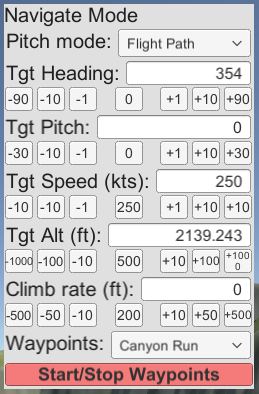
The GUI allows the pilot to select the autopilot mode: takeoff, navigation, or landing. In each mode, it displays options for setting parameters and selecting submodes. Each parameter comes with a few buttons to increase or decrease the value and a reset button that sets the parameter to a reasonable default.
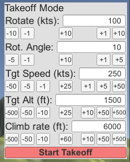
The takeoff mode GUI gives us control over the important parameters for takeoff. The user can set the rotation speed, climb rate, etc for the Takeoff mode here. The autopilot remains idle until the user clicks the “Start Takeoff” button.
The Navigation mode GUI lets the user select the pitch control mode and set the target values. Not every target value is used in every mode. “Tgt Pitch” controls either the target pitch or target flight path, depending on the mode. These are conceptually similar, so I combined them into one control.
The autopilot will enter or exit the waypoint following mode if the user clicks on the “Start/Stop Waypoints” button.
While landing is conceptually complicated, the GUI is not. All of the complexity is internal. The pilot controlled settings are quite simple. The landing starts when the user clicks the “Start Landing” button.
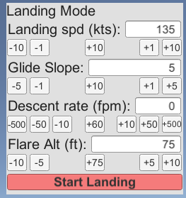
Actually, you could expose any of the parameters in landing mode through a GUI. I simply chose not to do that out of laziness.
This GUI system is somewhat similar to how real autopilots are used. For a video game NPC, these parameters can be set by a higher level AI system. This allows the AI to handle simple navigational tasks just by setting target altitude and heading.
Debugging
While the GUI display shows information that would be relevant to the pilot, there is a lot more information that is not shown. The autopilot takes in a few inputs from the pilot, but a majority of the input is calculated automatically from the plane’s state. Things like the plane’s current speed, altitude, or position are not set by the pilot. Intermediate values like distance to runway are calculated from these values.
These values are not displayed to the pilot because the sheer volume of information would be overwhelming. But they are useful to developers to see how the autopilot system is functioning internally. You can kind of already see these values by using the Unity inspector (in debug mode). But writing a custom debugging GUI gives the developer more control over variables that are relevant in a particular state.
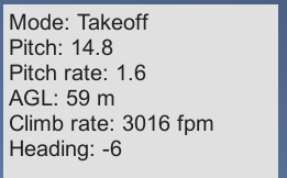
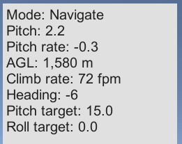
Takeoff and Navigation modes are fairly simple.
Because landing is more complicated, there is more information to display.
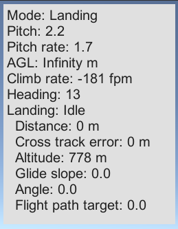
This gives the developer a real time display of certain variables and speeds up development. You can of course add whatever variables you want to the display. The GUI element is just a text label that is populated by a simple debug function in the autopilot code.
public void WriteDebugString(StringBuilder builder) {
    builder.AppendLine(string.Format("Mode: {0}", mode));

    float pitch = plane.PitchYawRoll.x;
    builder.AppendLine(string.Format("Pitch: {0:N1}", pitch));

    float pitchRate = -plane.LocalAngularVelocity.x * Mathf.Rad2Deg;
    builder.AppendLine(string.Format("Pitch rate: {0:N1}", pitchRate));

    float agl = plane.RadarAltimeter * Units.metersToFeet;
    builder.AppendLine(string.Format("AGL: {0:N0} m", agl));

    float climbRate = plane.Rigidbody.velocity.y * Units.metersToFeet * 60;
    builder.AppendLine(string.Format("Climb rate: {0} fpm", (int)Mathf.Round(climbRate)));
    builder.AppendLine(string.Format("Heading: {0:N0}", internalHeading));
}
You can add debug info for specific modes.
if (mode == AutopilotMode.Navigate) {
    builder.AppendLine(string.Format("Pitch target: {0:N1}", currentTargetPitch));
    builder.AppendLine(string.Format("Roll target: {0:N1}", currentTargetRoll));
} else if (mode == AutopilotMode.Landing) {
    builder.AppendLine(string.Format("Landing: {0}", landingMode.state));
    builder.AppendLine(string.Format("  Distance: {0:N0} m", currentLandingDistance));
    builder.AppendLine(string.Format("  Cross track error: {0:N0} m", currentLandingCrossTrack.Value));
    builder.AppendLine(string.Format("  Altitude: {0:N0} m", currentLandingAltitude));
    builder.AppendLine(string.Format("  Glide slope: {0:N1}", currentGlideSlope));
    builder.AppendLine(string.Format("  Angle: {0:N1}", currentLandingAngle));
    builder.AppendLine(string.Format("  Flight path target: {0:N1}", currentTargetFlightPath));
}
The current contents of the debug text are whatever I thought was most relevant the last time I changed this.
Conclusion
Writing an autopilot system seems like a daunting task. But as long as you know what to measure, you can control any aircraft in any situation. Real world autopilots are only a little more complicated than what I’ve written in this project.
Conversely, if you don’t know how to fly, just mentally execute this code. You’ve learned a new skill like Neo!
Try flying around in the test scene by changing the autopilot settings. Takeoff and fly around in Navigate mode. Try to set up a landing approach and then enter the Landing mode. You can still move the camera via the controller even when the autopilot is controlling the plane.
After enough time, you will see the weaknesses and limitations of this autopilot system. For example, the navigation system has no knowledge of the terrain. So the autopilot will happily fly into a mountain if you just set the heading and stop paying attention. (This is called controlled flight into terrain in the aviation industry)
The waypoint following mode has poor performance. You may see the plane suddenly tighten it’s turn as it passes the waypoint. This is because the calculation for target heading is simplistic. It sets the target heading towards the waypoint without considering distance. This can be improved by using the same cross track logic from the landing mode. In general, waypoint following logic can be improved with general AI navigation techniques to smooth pathing, but that’s outside the scope of this tutorial.
Writing an AI system that can use both the autopilot system and the combat AI from the previous part is left as an exercise for the reader. The systems from this article provide enough building blocks to write more complex behavior.
Any problem can be solved by breaking it down into smaller problems and solving it one at a time. The same techniques can be used to write an “autopilot” system for any vehicle and even character locomotion. You are only limited by how well you can measure the problem and your own understanding of it.